|
|
|
Categories
|
|
Information
|
|
Featured Product
|
|
|
 |
|
|
There are currently no product reviews.
 ;
I needed the manual immediately and I got it immediately. I couldn't find this manual anywhere else on the net. The site was easy to traverse, and the price was very reasonable. I'll definitely be back for any future needs.
 ;
I received a good service manual, with good resolution. Improve the instructions for the purchase because they are not well understood.
For the rest, so good.
Thanks Angel.
;
Very good documentation for the Grundig 2077 model (as well as similar 800/900/1000 series radios). The first two pages are a summary of reception specifications and output capability. The third page is the tuner dial indicator and dial cord routing diagram. the final ~5 pages are the schematics for the various models (including 2077). The scan quality of the schematics are good, adn can be easily read if zoomed in. The documents are in German, not English as stated. It would have been nice to have the tuning sequence and settings, and some trouble shooting materials... or component and wiring map.
;
Perfect like it was descriped, Perfect like it was descriped
;
Very good detail, all pages clear, exactly what I needed
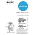
ADJ 6
Copy image distortion adjustment
3) Loosen the pulley angle fixing screw on the front frame side of the scanner unit B.
This adjustment must be performed in the following cases: � When the scanner (reading) section is disassembled. � When a copy image distortion occurs.
ADJ 6A
Scanner (reading) unit parallelism adjustment
1) Loosen the screw that is fixing the scanner unit A and the drive wire, and remove the scanner unit A from the drive wire.
4) Adjust the pulley angle position on the scanner unit B front frame side so that both stoppers on the front frame and the rear frame are in contact with the scanner unit B at the same time. 5) Fix the pulley angle on the scanner unit B front frame side. If the above procedure does not result in a satisfactory result, perform the following procedure. Loosen the fixing screw of the scanner unit drive pulley that is not in contact. Without moving the scanner unit drive shaft, manually turn the scanner unit drive pulley so that the scanner unit B is brought into contact with the stopper on the front frame side and the stopper on the rear frame side at the same time. (Change the relative positions of the scanner unit drive pulley and the drive shaft.) Fix the scanner unit drive pulley fixing screw.
Scanner unit B
2) Manually turn the scanner drive pulley to bring the scanner unit B into contact with the stopper. At that time, if the scanner unit B makes contact with the two stoppers on the front and the rear frame simultaneously, the parallelism of the scanner unit B is proper. If not, perform the following procedures.
Winding pulley
AR-C172M SETTING AND ADJUSTMENTS 8 - 15
|
|
|
> |
|