|
|
|
Categories
|
|
Information
|
|
Featured Product
|
|
|
 |
|
|
There are currently no product reviews.
 ;
Excellent printing quality.
A complete and very usefull service manual with all details.
GREAT SERVICE AT VERY LOW PRICE!
A+++++++++++++++++++++++++
;
Excellent printing quality.
A complete and very usefull service manual with all details.
GREAT SERVICE AT VERY LOW PRICE!
A+++++++++++++++++++++++++
;
SATELLIT 4000 GRUNDIG
Service Manual
high quality. good graphics. prompt service.
;
Excellent printing quality.
A complete and very usefull service manual with all details.
GREAT SERVICE AT VERY LOW PRICE!
A+++++++++++++++++++++++++
;
Excellent printing quality.
A complete and very usefull service manual with all details.
GREAT SERVICE AT VERY LOW PRICE!
A+++++++++++++++++++++++++
ADJ 6
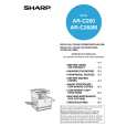
Copy image distortion adjustment
3) Loosen the pulley angle fixing screw on the front frame side of the scanner unit B.
This adjustment must be performed in the following cases: � When the scanner (reading) section is disassembled. � When a copy image distortion occurs.
ADJ 6A
Scanner (reading) unit parallelism adjustment
1) Loosen the screw that is fixing the scanner unit A and the drive wire, and remove the scanner unit A from the drive wire.
4) Adjust the pulley angle position on the scanner unit B front frame side so that both stoppers on the front frame and the rear frame are in contact with the scanner unit B at the same time. 5) Fix the pulley angle on the scanner unit B front frame side. If the above procedure does not result in a satisfactory result, perform the following procedure. Loosen the fixing screw of the scanner unit drive pulley that is not in contact. Without moving the scanner unit drive shaft, manually turn the scanner unit drive pulley so that the scanner unit B is brought into contact with the stopper on the front frame side and the stopper on the rear frame side at the same time. (Change the relative positions of the scanner unit drive pulley and the drive shaft.) Fix the scanner unit drive pulley fixing screw.
Scanner unit B
2) Manually turn the scanner drive pulley to bring the scanner unit B into contact with the stopper. At that time, if the scanner unit B makes contact with the two stoppers on the front and the rear frame simultaneously, the parallelism of the scanner unit B is proper. If not, perform the following procedures.
Winding pulley
AR-C260/C260M SETTING AND ADJUSTMENTS 8 - 16
|
|
|
> |
|