|
|
|
Categories
|
|
Information
|
|
Featured Product
|
|
|
 |
|
|
There are currently no product reviews.
 ;
This manual was exactly what i needed and could not find elsewhere. Price is not too high. Great !
;
ecelent I was reciver the service manual soon I fell so happy very complete 100% positive all by this store tanks atte Luis salazar
 ;
A great copy of the manual, and the only one I could find anywhere on the net! The circuit diagrams are easily readable, all component values marked and easy to see. A highly appreciated download!
;
Great Manual. This manual is available no where else. It was exactly what I was looking for.
;
The TEAC A-1500's Service Manual was instrumental in reviving this classic reel-to-reel. Not only does it have the schematics, exploded parts diagram and parts list, it also provided mechanical adjustment information that approximate factory default settings.
Allgemeiner Teil / General Section
CUC 1931
Ausbauhinweise
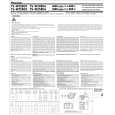
Vor dem �ffnen des Gehäuses zuerst den Netzstecker ziehen! Leitungsverlegung Bevor Sie die Leitungen und insbesondere die Masseleitungen lösen, muss die Leitungsverlegung zu den einzelnen Baugruppen wie z.B. Chassis, Netzschalterplatte, Bedieneinheit, Bildrohrplatte, Ablenkeinheit, Lautsprecher usw. beachtet werden. Nach erfolgter Reparatur ist es notwendig, die Leitungsführung wieder in den werkseitigen Zustand zu versetzen um eventuell spätere Ausfälle oder Störungen zu vermeiden. �ffnen des Gehäuses - 8 Rückwandschrauben herausschrauben. - Gehäuserückwand vorsichtig nach hinten abnehmen bis die Subwoofer-Leitung gelöst werden kann. 1. DVD-Einheit ausbauen - 2 Schrauben A (Fig. 1, 2) herausschrauben und DVD-Einheit entnehmen, gegebenenfalls Leitungen lösen. Achtung: Leitungsverlegung beachten!
Disassembly Instructions
Before opening the cabinet disconnect the mains plug! Wiring Before disconnecting any leads and especially the earth connecting leads observe the way they are routed to the individual assemblies like the chassis, mains switch panel, keyboard control panel, picture tube panel, deflection unit, loudspeaker and so on. On completion of the repairs the leads must be laid out as originally fitted at the factory to avoid later failures or disturbances. Opening the cabinet - Undo the 8 screws in the rear panel. - Remove the rear panel carefully to the rear until the subwoofer lead can be disengaged. 1. Removing the DVD unit - Undo the 2 screws A (Fig. 1, 2) then remove the DVD unit. Disconnect the leads if necessary. Attention: observe the way the leads are routed!
Fig. 1
A
Fig. 2
A
2. Chassis ausbauen - DVD-Einheit ausbauen (Pkt. 1). - 2 Schrauben B (Fig. 3, 4) herausschrauben und Chassis nach hinten herrausziehen, gegebenenfalls Kabelbinder und Leitungen lösen. Achtung: Leitungsverlegung beachten!
2. Removing the chassis - Remove the DVD unit (para 1). - Undo the 2 screws B (Fig. 3, 4) then pull out the chassis to the rear. If necessary undo the cable clamps and disconnect the leads. Attention: observe the way the leads are routed!
Fig. 3
B
Fig. 4
B
6
GRUNDIG Service
|
|
|
> |
|