|
|
|
Categories
|
|
Information
|
|
Featured Product
|
|
|
 |
|
|
There are currently no product reviews.
 ;
Fully functional usable service manual. Considering the age of the manual and device quality was better than expected
 ;
Thank you very much, I've been very happy to find this manual on "Owner Manual". It's a perfect copy and it has been really useful for my work!
;
It took about 24-hours after my payment before I was able to get to the download. Apparently, payment processing is not 100% automated. That is no big deal, just be aware of that going in.
After I got to it, it was in good shape, easy to read, etc. Not some cheap FAX copy looking thing.
Also, this site was the cheapest I found. Another Plus!
;
Good price, very legible manual, exactly what I needed -- but had to wait a day to actually get the download of the manual. Would have preferred to download it immediately after payment rather than waiting for someone to "process" my order. I was surprised that I had to wait that long.
;
As the only source for this manual it rather rank quite high since it is well scanned and perfectly readable.
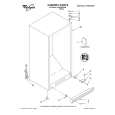
CPU (HD6433298A36P)
The 16-bit CPU contains a 32k-bit ROM, a 1k-bit RAM, seven 8-bit I/O ports, an A/D convertor and serial interfaces. The CPU accesses to the working strage RAM, the DSP and the key touch LSI. The CPU also controls buttons, bender input, LEDs and MIDI input/output. The following table shows the pin functions of the CPU. Pin No. 1 2 3 4 5 6 7 8 9 10 11 12 13 14 15 16 17, 18 19, 20 21 22 23 ~ 29 30 31 ~ 38 39 40 41 ~ 56 48 57 ~ 64 Terminal P40 P41 P42 P43 P44 P45 P46 P47 TXD RXD P52 -RESET -NMI VCC -STBY VSS XTAL,EXTAL MD1, MD0 AVSS AN0 P71 ~ P77 AVCC P60 ~ P67 VCC P27 P26 ~ P10 VSS P30 ~ P37 Out In In/Out Out In Out In Out In In In In In In In In In In In Out In In/Out Out Out Out Out Out KO signal data output Clock for KO signal data APO (Auto Power Off) signal output. ON: High OFF: Low Read enable signal output Write enable signal output Not used 10 MHz clock output Wait signal input. Connected to +5 V. MIDI signal output MIDI signal input Reset signal output Reset signal input Power ON signal input +5 V source Standby signal input. Connected to +5 V. Ground (0 V) source 20 MHz clock input Mode selection input.(Internal ROM mode --- MD1: High MD0: Low) Ground (0 V) source for the built-in DAC Analog input. Connected to ground. Ternimal for button input signal +5 V source for the built-in DAC LED segment signal output +5 V source Not used Address bus Ground (0 V) source Data bus Function
Digital Signal Processor (HG51B155FD)
Upon receipt of note numbers and their velocities, the DSP reads sound and velocity data from the sound source ROM in accordance with the selected tone; the DSP can read rhythm data simultaneously when a rhythm pattern is selected. Then it provides 16-bit serial signals containing data of the melody, chord, bass, and percussion to the DAC. The DSP also adds the selected effect to the sound data using a 64k-bit RAM. The following table shows the pin functions of the DSP.
�6�
 $4.99 AT1 CASIO
Owner's Manual Complete owner's manual in digital format. The manual will be available for download as PDF file aft…
|
|
|
> |
|