|
|
|
Categories
|
|
Information
|
|
Featured Product
|
|
|
 |
|
|
There are currently no product reviews.
 ;
Sweet! I won the item on eBay and couldn't adjust the geometry or even keep a steady picure. This guide has the full schematics (not available anywhere else as far as I could tell), and was a bargain for the wealth of knowledge it contains. I hooked it up to my testing equipment, tweaked a few potentiometers and got it playing videogames in no time. Thanks!
;
It was just what I need to fix my old BMW's CD player. Very convenient also. Thank you.
;
Great Manual! It contains all the wiring schematics and mechanical exploded views that are essential for service and repair. I was surprised I even found this for such an old machine. Only wish I knew of this site many years ago.
;
Great manual very clear copied. You are making an incredible job. I appreciate a lot the rapidity and your efficiency. Thanks a lot
;
Good pdf of the service manual for this unit. Includes disassembly instructions, full schematics, board layouts, parts lists and diagnostic information. Some information is in the pdf twice (single pages, and split pages), but that could be how it was originally generated by panasonic, or perhaps the idea is to make it eaiser to put onto 8.5 x 11" pages.
Information was exactly what I needed. Delivery was overnight (less than 12 hours) and I was happy with the process.
AV-14A3 AV-1415EE AV-14AMG3
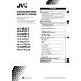
REPLACEMENT OF CHIP COMPONENT
! CAUTIONS
1. 2. 3. 4. Avoid heating for more than 3 seconds. Do not rub the electrodes and the resist parts of the pattern. When removing a c hip part, melt the s older adequately. Do not reuse a chip part after removing it.
! SOLDERING IRON
1. Use a high ins ulation s oldering iron with a thin pointed end of it. 2. A 30w s oldering iron is rec ommended for easily removing parts.
! REPLACEMENT STEPS
1. How to remove Chip parts $ Resistors, capacitors, etc (1) As shown in the figure, push the part with tweezers and alternately melt the solder at each end.
2. How to install Chip parts
$ Resistors, capacitors, etc (1) Apply solder to the pattern as indic ated in the figure.
(2) Grasp the chip part with tweezers and plac e it on the s older. (2) Shift with tweezers and remove the chip part. Then heat and melt the solder at both ends of the chip part.
$ Transistors, diodes, variable r esistor s, etc (1) Apply extra solder to each lead.
$ Transistors, diodes, variable r esistor s, etc (1) Apply solder to the pattern as indic ated in the figure. (2) Grasp the chip part with tweezers and place it on the solder. (3) First s older lead A as indicated in the figure.
SOLD E R
SOLD E R
(2) As shown in the figure, push the part with tweezers and alternately melt the solder at each lead. Shift and remove the chip part.
A B C (4) Then solder leads B and C.
A B Note : After removing the part, remove remaining solder from the pattern. C
No.52029
31
|
|
|
> |
|