|
There are currently no product reviews.
 ;
Exellent manual ,it was in great condition,and got all the info i expected,5 stars!!
;
I searched the Internet exhaustively for this manual and Owner-Manuals was the least expensive...but provided an excellent reproduction within 4 hours. Very satisified.
 ;
Rapid and precise delivery. Good print. On the spot.
;
available for me the service manual is in order!
thanks
;
This is exactly the thing you need to service this box. The manual is complete and the quality of the scan is good. I recommend this!
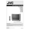
AV-20D304
2.2 DISASSEMBLY PROCEDURE 2.2.1 REMOVING THE REAR COVER (1) Unplug the power plug. (2) As shown in the Fig.1, remove the 9 screws [A]. (3) As shown in Fig.1, remove the 4 screws [B]. (4) Then remove the REAR COVER toward you. 2.2.4 CHECKING THE PW BOARD � Remove the REAR COVER. (1) Pull out the MAIN CHASSIS (refer to REMOVING THE MAIN PWB). (2) Erect the MAIN CHASSIS vertically so that you can easily check the backside of the PW Board. CAUTION: � When erecting the chassis, be careful so that there will be no contacting with other PW Board. � Before turning on power, make sure that the wire connector is properly connected. � When conducting a check with power supplied, be sure to confirm that the CRT EARTH WIRE (BRAIDED ASS�Y) is onnected to the CRT SOCKET PW board. 2.2.3 REMOVING THE SPEAKER � Remove the REAR COVER. (1) As shown in Fig.1, remove the 4 screws [D], then remove the speaker. (2) Follow the same steps when remove the other hand speaker. NOTE: When removing the 4 screws [D] of the speaker, remove the lower side screw first, and then remove the upper one. 2.2.5 WIRE CLAMPING AND CABLE TYING (1) Be sure to clamp the wire. (2) Never remove the cable tie used for tying the wires together. Should it be inadvertently removed, be sure to tie the wires with a new cable tie.
2.2.2 REMOVING THE MAIN PWB � Remove the REAR COVER. (1) Raise the backside of the MAIN PWB, and remove the PWB STOPPER [C] from the cabinet. (2) Withdraw the MAIN PWB backward. (If necessary, remove the wire clamp, connectors etc.)
(No.52103)1-5
|