|
|
|
Categories
|
|
Information
|
|
Featured Product
|
|
|
 |
|
|
There are currently no product reviews.
 ;
A good and useful manual. With these, We was abled to isolate and pin point the component that was causing the problem. The total time spent in troubleshooting is very much reduced.
 ;
The quality of the manual is top. The transfer worked perfect and fast.
No problems at all. Recommendable
;
Very good service for get any documentation. Fast and perfect quality.
;
Excellent service manual with all the necessary info. :)
;
The product dowload was delivered efficiently with emails to support its download availabilty. The contets of the manual was very eligible and of good quality. Will purchase from this site again!
AV-20F703
ELECTRICAL ADJUSTMENTS
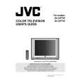
2-6: HORIZONTAL POSITION 1. Receive the monoscope pattern. 2. Using the remote control, set the brightness and contrast to normal position. 3. Activate the adjustment mode display of Fig. 1-1 and press the channel button (04) on the remote control to select �H. POSI�. 4. Press the VOL. UP/DOWN button on the remote control until the SHIFT quantity of the OVER SCAN on right and left becomes minimum. 2-7: VERTICAL POSITION Receive the monoscope pattern. 1. 2. Using the remote control, set the brightness and contrast to normal position. 3. Activate the adjustment mode display of Fig. 1-1 and press the channel button (05) on the remote control to select �V. POSI�. 4. Press the VOL. UP/DOWN button on the remote control until the horizontal line becomes fit to the notch of the shadow mask. 2-8: VERTICAL SIZE 1. Receive the monoscope pattern. 2. Using the remote control, set the brightness and contrast to normal position. 3. Activate the adjustment mode display of Fig. 1-1 and press the channel button (07) on the remote control to select �V. SIZE�. 4. Press the VOL. UP/DOWN button on the remote control until the SHIFT quantity of the OVER SCAN on upside and downside becomes 9 ± 2%. 2-9: VERTICAL LINEARITY NOTE: Adjust after performing adjustments in section 2-8. After the adjustment of Vertical Linearity, reconfirm the Vertical Position and Vertical Size adjustments. 1. Receive the monoscope pattern. 2. Using the remote control, set the brightness and contrast to normal position. 3. Activate the adjustment mode display of Fig. 1-1 and press the channel button (09) on the remote control to select �V. LIN�. 4. Press the VOL. UP/DOWN button on the remote control until the SHIFT quantity of the OVER SCAN on upside and downside becomes minimum. 2-10: LEVEL 1. Receive the monoscope pattern (70dB). 2. Connect the AC voltmeter to pin 6 of CP101 and the pin 1 (GND) of CP101. 3. Activate the adjustment mode display of Fig. 1-1 and press the channel button (36) on the remote control to select �LEVEL�. 4. Press the VOL. UP/DOWN button on the remote control until the AC voltmeter is 75 ± 2mV. 2-11: SUB BRIGHTNESS 1. Activate the adjustment mode display of Fig. 1-1 and press the channel button (16) on the remote control to select �BRI. CENT�. 2. Press the VOL. UP/DOWN button on the remote control until the brightness step No. becomes �50�. 3. Receive a broadcast and check if the picture is normal. 4. Press the INPUT button on the remote control to set to the AV mode. Then perform the above adjustments 1~3. 5. Press the INPUT button on the remote control to set to the CS mode. Then perform the above adjustments 1~3. 2-12: TINT/COLOR CENT 1. Receive the color bar pattern. (RF Input) 2. Connect the oscilloscope to TP806. 3. Using the remote control, set the brightness, contrast, color and tint to normal position. 4. Activate the adjustment mode display of Fig. 1-1 and press the channel button (26) on the remote control to select �TINT�. 5. Press the VOL. UP/DOWN button on the remote control until the section �A� becomes a straight line (Refer to Fig. 2-1). 6. Connect the oscilloscope to TP804. 7. Press the channel button (24) on the remote control to select �COL. CENT�. 8. Adjust the VOLTS RANGE VARIABLE knob of the oscilloscope until the range between white 100% and 0% is set to 4.4 scales on the screen of the oscilloscope. 9. Press the VOL. UP/DOWN button on the remote control until the red color level is adjusted to 115 ± 10% of the white level. (Refer to Fig. 2-2) 10. Receive the color bar pattern. (Audio Video Input) 11. Press the INPUT button on the remote control to set to the AV mode. Then perform the above adjustments 2~9. 12. Press the INPUT button on the remote control to set to the CS mode. 13. Activate the adjustment mode display of Fig. 1-1 and press the channel button (26) on the remote control to select �TINT�. 14 Press the VOL. UP/DOWN button on the remote control until the tint step No. becomes �50�. 15. Press the channel button (24) on the remote control to select �COL. CENT�. 16. Press the VOL. UP/DOWN button on the remote control until the color step No. becomes �62�. 17. Receive a broadcast and check if the picture is normal.
�A� Fig. 2-1
10
No. 52001
 $4.99 AV-20F703 JVC
User Guide It's a complete guide ( also known as operating manual or owner's manual), and it's in PDF format. A…
|
|
|
> |
|


