|
|
|
Categories
|
|
Information
|
|
Featured Product
|
|
|
 |
|
|
There are currently no product reviews.
 ;
This Service Manual was exactly what I needed to repair my Philips TV. The purchase was convenient and I received the manual at the same day I paid for it.
;
Very pleased with the whole process. Great commication and very easy instructions to order and to download the manual.
;
It's a good manual, this one it's a scan from the original factory service manual, great quality 100% readeable. definetely it worths what I paid for.
 ;
A good manual! fast service and good qualityi for pdf document.
thanks!
;
Very helpful and complete manual. Maybe only one negative is schematics have sometimes unreadable name of the parts. But it's not a big problem.
AV-20F704
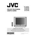
2-7: VERTICAL POSITION 1. Receive the monoscope pattern. 2. Using the remote control, set the brightness and contrast to normal position. 3. Adjust the VR401 until the horizontal line becomes fit to the notch of the shadow mask. 2-8: VERTICAL SIZE 1. Receive the monoscope pattern. 2. Using the remote control, set the brightness and contrast to normal position. 3. Activate the adjustment mode display of Fig. 1-1 and press the channel button (07) on the remote control to select �V. SIZE�. 4. Press the VOL. UP/DOWN button on the remote control until the SHIFT quantity of the OVER SCAN on upside and downside becomes 9 ± 2%. 2-9: VERTICAL LINEARITY NOTE: Adjust after performing adjustments in section 2-8. After the adjustment of Vertical Linearity, reconfirm the Vertical Position and Vertical Size adjustments. 1. Receive the monoscope pattern. 2. Using the remote control, set the brightness and contrast to normal position. 3. Activate the adjustment mode display of Fig. 1-1 and press the channel button (08) on the remote control to select �V. LIN�. 4. Press the VOL. UP/DOWN button on the remote control until the SHIFT quantity of the OVER SCAN on upside and downside becomes minimum. 2-10: OSD HORIZONTAL 1. Activate the adjustment mode display of Fig. 1-1. 2. Press the VOL. UP/DOWN button on the remote control until the difference of A and B becomes minimum. (Refer to Fig. 2-1)
2-11: SEPARATION 1, 2 Please do the method (1) or method (2) adjustment. Method (1) 1. Set the multi-sound signal generator for each different Lch and R-ch frequency (Ex. L-ch=2KHz, R-ch=400Hz) and receive the RF. 2. Connect the oscilloscope to the Audio Out Jack. 3. Activate the adjustment mode display of Fig. 1-1 and press the channel button (34) on the remote control to select �SEP1�. 4. Press the VOL. UP/DOWN button on the remote control to adjust it until the audio output wave becomes a fine sine wave. 5. Press the CH UP button once the set to �SEP 2� mode. Then perform the above adjustment 4. Method (2) 1. Set the multi-sound signal generator L-ch=1KHz, R-ch=Non input and receive the RF. 2. Connect the oscilloscope to the Audio Out Jack (R-ch). 3. Press the AUDIO SELECT button on the remote control to set to the stereo mode. 4. Activate the adjustment mode display of Fig. 1-1 and press the channel button (34) on the remote control to select �SEP 1�. 5. Press the VOL. UP/DOWN button on the remote control to adjust it until the R-ch output becomes minimum. 6. Set the multi-sound signal generator L-ch=Non input, R-ch=1KHz and receive the RF. 7. Connect the oscilloscope to the Audio Out Jack (L-ch). 8. Activate the adjustment mode display of Fig. 1-1 and press the channel button (35) on the remote control to select �SEP 2�. 9. Press the VOL. UP/DOWN button on the remote control to adjust it until the L-ch output becomes minimum. 2-12: BRIGHT CENTER 1. Receive the monoscope pattern. (RF Input) 2. Using the remote control, set the brightness and contrast to normal position. 3. Activate the adjustment mode display of Fig. 1-1 and press the channel button (16) on the remote control to select �BRI. CENT�. 4. Press the VOL. UP/DOWN button on the remote control until the white 15% is starting to be visible. 5. Receive the monoscope pattern. (Audio Video Input) 6. Press the TV/VCR button on the remote control to set to the AV mode. Then perform the above adjustments 2~4. 7. Press the TV/VCR button on the remote control to set to the CS mode. 8. Activate the adjustment mode display of Fig. 1-1 and press the channel button (16) on the remote control to select �BRI. CENT�. 9. Press the VOL. UP/DOWN button on the remote control to set the same step numbers as the AV.
TV
00 OSD A
35 B
Fig. 2-1
No. 52131
9
|
|
|
> |
|