|
|
|
Categories
|
|
Information
|
|
Featured Product
|
|
|
 |
|
|
There are currently no product reviews.
 ;
The manual for the Sansui P-L75 was not one of the more informative turntable manuals around but for $5 it was helpful enough.
;
VERY GOOD SERVICE.FAST ANS VERY HONEST PRICE .RHAANK HERNAN
 ;
Thanks to this service manual I repaired my old camcorder! The manual perfectly explains how to disassemble the camcorder step by step.
;
This manual is very useful because it presents the technical specifications of the cd player, including the manufacturer of the reader, this helps if you need to replace it. It also displays the settings and layout of the circuit.
;
Manual was a good representation of service infomation for the EWV404. It worked well for my repair.
AV-20FD23
ELECTRICAL ADJUSTMENTS
2-11: SEPARATION Please do the method (1) or method (2) adjustment. Method (1) 1. Set the multi-sound signal generator for each different Lch and R-ch frequency (Ex. L-ch=2KHz, R-ch=400Hz) and receive the RF signal. 2. Connect the oscilloscope to the Audio Out Jack. 3. Press the AUDIO button on the remote control to set to the stereo mode. 4. Activate the adjustment mode display of Fig. 1-1 and press the channel button (70) on the remote control to select �SEPAL�. 5. Press the VOL. UP/DOWN button on the remote control to adjust it until the audio output wave becomes a fine sine wave. 6. Press the CH UP button 1 time to set to "SEPAH" mode. 7. Press the VOL. UP/DOWN button on the remote control to adjust it until the audio output wave becomes a fine sine wave. Method (2) 1. Set the multi-sound signal generator L-ch=1KHz, R-ch =Non input and receive the RF signal. 2. Connect the oscilloscope to the Audio Out Jack (R-ch). 3. Press the AUDIO button on the remote control to set to the stereo mode. 4. Activate the adjustment mode display of Fig. 1-1 and press the channel button (70) on the remote control to select �SEPAL�. 5. Press the VOL. UP/DOWN button on the remote control to adjust it until the R-ch output becomes minimum. 6. Press the CH UP button 1 time to set to "SEPAH" mode. 7. Press the VOL. UP/DOWN button on the remote control to adjust it until the R-ch output becomes minimum. 8. Set the multi-sound signal generator L-ch=Non input, R-ch=1KHz and receive the RF signal. 9. Connect the oscilloscope to the Audio Out Jack (L-ch). Then perform the above adjustments 3~7. 2-12: LEVEL 1. Receive the VHF HIGH (70dB). 2. Connect the AC voltmeter to pin 6 of CP101. 3. Activate the adjustment mode display of Fig. 1-1 and press the channel button (69) on the remote control to select "LVL". 4. Press the VOL. UP/DOWN button on the remote control until the AC voltmeter is 72 ± 2mV. 2-13: BRIGHT CENTER 1. Receive the monoscope pattern. (RF Input) 2. Using the remote control, set the brightness and contrast to normal position. 3. Activate the adjustment mode display of Fig. 1-1 and press the channel button (06) on the remote control to select "BRTC". 4. Press the VOL. UP/DOWN button on the remote control until the white 15% is starting to be visible. 5. Receive the monoscope pattern. (Audio Video Input) 6. Press the INPUT button on the remote control to set to the AV mode. 7. Using the remote control, set the brightness and contrast to normal position. 8. Activate the adjustment mode display of Fig. 1-1 and press the channel button (37) on the remote control to select "BRTCA". 9. Press the VOL. UP/DOWN button on the remote control until the white 15% is starting to be visible. 10. Press the TV/DVD button on the remote control to set to the DVD mode. 11. Activate the adjustment mode display of Fig. 1-1 and press the channel button (49) on the remote control to select "BRTCD". 12. Press the VOL. UP/DOWN button on the remote control to set the same step numbers as the AV. 2-14: SUB TINT CENTER 1. Receive the color bar pattern. (RF Input) 2. Using the remote control, set the brightness, contrast, color and tint to normal position. 3. Connect the oscilloscope to TP024. 4. Activate the adjustment mode display of Fig. 1-1 and press the channel button (12) on the remote control to select "TNTC". 5. Press the VOL. UP/DOWN button on the remote control until the section "A" becomes a straight line. (Refer to Fig. 2-2) 6. Receive the color bar pattern. (Audio Video Input) 7. Press the INPUT button on the remote control to set to the AV mode. 8. Using the remote control, set the brightness, contrast, color and tint to normal position. 9. Activate the adjustment mode display of Fig. 1-1 and press the channel button (43) on the remote control to select "TNTCA". 10. Press the VOL. UP/DOWN button on the remote control until the section "A" becomes a straight line. (Refer to Fig. 2-2) 11. Press the TV/DVD button on the remote control to set to the DVD mode. 12. Activate the adjustment mode display of Fig. 1-1 and press the channel button (55) on the remote control to select "TNTCD". 13. Press the VOL. UP/DOWN button on the remote control until the tint step No. becomes "49"
18
No. 52014
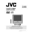 $4.99 AV-20FD23 JVC
User Guide It's a complete guide ( also known as operating manual or owner's manual), and it's in PDF format. A…
|
|
|
> |
|