|
|
|
Categories
|
|
Information
|
|
Featured Product
|
|
|
 |
|
|
There are currently no product reviews.
 ;
Great manual...really saved me. The only problem is that I thought I would be able to download it directly when I paid for it but never received the download instructions until the next morning. The board trace pages were somewhat light also: really need to turn up the contrast on the printer before printing them. The schematic page was great; very clear! Well worth the money.
 ;
I've been in the electronic business for a long time. I used to buy Sam's Photofact for my needs which intailed having to go to the store and paying about $20 for a package of 3 different units so I was forced to buy more than I needed just to get one.
Owner manual is just at your keyboard and the information is almost instantansouly and the cost is very reasonable. Easy to print out if needed or simply read off of the screen. The larger the screen the better for obvious reasons.
;
Very good manual, at a very good price. Received in a timely manner
;
Only thу cover has poor quality, internal material has excellent quality - exactly what I needed
Thanks!
;
Had everything I needed. Onyly took a few hours after paid for by PayPal. The copy was very readable.
AV-20N3PX
REPLACEMENT OF CHIP COMPONENT
s CAUTIONS
1. 2. 3. 4. Avoid heating for more than 3 seconds. Do not rub the electrodes and the resist parts of the pattern. When removing a chip part, melt the solder adequately. Do not reuse a chip part after removing it.
s SOLDERING IRON
1. Use a high insulation soldering iron with a thin pointed end of it. 2. A 30W soldering iron is recommended for easily removing parts.
s REPLACEMENT STEPS 1. How to remove Chip parts
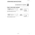
q Resistors, capacitors, etc. (1) As shown in the figure, while pushing the chip part with tweezers, alternately melt the solder at its each end.
2. How to install Chip parts
q Resistors, capacitors, etc. (1) Apply solder to the pattern as indicated in the figure.
(2) Grasp the chip part with tweezers and place it on the solder. Then heat and melt the solder at both ends of the chip part. (2) Shift the chip part with tweezers and remove it.
q Transistors, diodes, variable resistors, etc. (1) Apply extra solder to each lead.
q Transistors, diodes, variable resistors, etc. (1) Apply solder to the pattern as indicated in the figure. (2) Grasp the chip part with tweezers and place it on the solder. (3) First solder lead A as indicated in the figure.
SOLDER
SOLDER
A (2) As shown in the figure, while pushing the chip part with tweezers, alternately melt the solder at its each lead. Then, shift and remove the chip part. B C (4) Then solder leads B and C. A B C
Note : After removing the part, remove remaining solder from the pattern.
No. 56049
9
|
|
|
> |
|