|
|
|
Categories
|
|
Information
|
|
Featured Product
|
|
|
 |
|
|
There are currently no product reviews.
 ;
Easy and secure way to get a complete service manual of a vintage hifi component. Only some parts of the print copy are dificult to read. Nice price!
 ;
The manual is an excellent reproduction with complete schematics, made troubleshooting and repair a simple process.
;
Up to now you are the BEST! Prompt-efficient and so reasonable ! I have been after SONY service manual for quite some time !Thank you very much ! I can recomend your service to
all my collegagues ! V.Bergfield .
;
This is a very good quality print (scan) of the original SONY service manual. The original from Sony is on very thin paper. Nevertheless it is very clear and sharp and excellent readable. I'm very satisfied to have now this rare document. I've looking for it many years (infrequent). It contains very detailed circuit diagrams, exploded views, part lists, PCB view with good readable connection lines. Very recommended.
;
A complete manual with all the needed details of calibrations and service instructions about the radio receiver.
A big deal.
Many thanks !
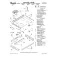
AV-21L31 AV-25L31
REMOVING THE CRT
* Replacement of the CRT should be performed by 2 or more persons.
CRT CHANGE TABLE
� After removing the rear cover, chassis etc.,
1. Putting the CRT change table on soft cloth, the CRT change table should also be covered with such soft cloth (shown in Fig. 2). 2. While keeping the surface of CRT down, mount the TV set on the CRT change table balanced will as shown in Fig. 3. 3. Remove 4 screws marked by arrows with a box type screwdriver as shown in Fig. 3. Since the cabinet will drop when screws have been removed, be sure to support the cabinet with hands. 4. After 4 screws have been removed, put the cabinet slowly on cloth (At this time, be carefully so as not to damage the front surface of the cabinet) shown in Fig. 4. The CRT should be assembled according to the opposite sequence of its dismounting steps.
APPROX. 35cm CLOTH
�
Fig. 2
�
CRT
* The CRT change table should preferably be smaller that the CRT surface, and its height be about 35cm.
CRT CHANGE TABLE BOX TYPE SCREW DRIVER
Fig. 3
CRT
COATING OF SILICON GREASE FOR ELECTRICAL INSULATION ON THE CRT ANODE CAP SECTION.
� Subsequent to replacement of the CRT and HV transformer or repair
of the anode cap, etc. by dismounting them, be sure to coat silicon grease for electrical insulation as shown in Fig. 5. 1. Wipe around the anode button with clean and dry cloth. (Fig. 5) 2. Coat silicon grease on the section around the anode button. At this time, take care so that any silicon greases does not sticks to the anode button. (Fig. 6) Silicon grease product No. KS - 650N
CABINET
CRT CHANGE TABLE
Fig. 4
CRT
Anode button
Approx. 20mm (Do not coat grease on this section
Silicon grease should be coated by 5mm or more from the outside diameter of anode cap.
Silicon grease coating
Anode button (No sticking of silicon grease)
Coating position of silicon grease Anode cap
Fig. 5
Fig. 6
8
No. 51908
|
|
|
> |
|