|
|
|
Categories
|
|
Information
|
|
Featured Product
|
|
|
 |
|
|
There are currently no product reviews.
 ;
got exactly what i ordered in a very timely manner. will use again for other manuals
 ;
I'm happy. Good quality. Very helped me with my work..............................
;
This is the second Manual I have ordered from owner-manuals, I give it five stars because it is exactly what I expected given the age of the equipment. So the contents look a bit aged and the pictures a bit grainy, it fulfills my needs and I am glad I can still get hold of them.
;
thank u so much for this manual that was so cheap that i thought it was a scam but i gambled anyway because it was too good of a deal to pass up and behold,the manual has everything and details of everything even the screws and im still amazed and very happy with my manual .so take my word and jump on it before they realize how cheap they selling thier manuals..thank you so much for taking time to read my thoughts
;
I do not have very much to say.
The price is quite covenient, delivery was better as promised (about 12 ours, against the specified 24 hours if I remember well), and the quality of the PDF is more than acceptable.
The Service Manual of Sansui R30 itself is also satisfactory: good graphic for schematics and layouts, simple and well structured.
Giovanni Bianchi
AV-21D83
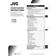
DISASSEMBLY PROCEDURE [AV-21D83/BK, AV-21D83/VT]
REMOVING THE REAR COVER
1. Unplug the power supply cord. 2. Remove the 7 screws marked � and 4 screws marked ı as shown in Fig.1. 3. Withdraw the Rear cover toward you. [CAUTION] When reinstalling the rear cover, carefully push it inward after inserting the Main PWB into the rear cover groove.
�
REMOVING THE MAIN PW BOARD
� After removing the rear cover.
1. Slightly raise the both sides of the Main PWB by hand, take off the PB Stopper marked � from the front cabinet. 2. Withdraw the Main PWB backward. (If necessary, take off the wire clamp and connectors, etc.)
REMOVING THE SPEAKER [AV-21D83/BK]
� After removing the rear cover.
1. Remove the 2 screws marked � as shown in Fig.1. 2. Follow the same steps when removing the other hand speaker.
REMOVING THE SPEAKER [AV-21D83/VT]
� After removing the rear cover.
1. Remove the 2 screws marked � and 2 screws marked ´ as shown in Fig.1. 2. Follow the same steps when removing the other hand speaker.
CHECKING THE MAIN PW BOARD
1. To check the back side of the Main PWB. 1) Pull out the Main PWB. (Refer to REMOVING THE MAIN PW BOARD). 2) Erect the Main PWB vertically so that you can easily check its back side. [CAUTION] Before turning on power, make sure that the CRT earth wire and other connectors are properly connected. When repairing, connect the Deg. coil to the DEG. connector on the Main PWB.
� �
WIRE CLAMPING AND CABLE TYING
1. Be sure to clamp the wire. 2. Never remove the cable tie used for tying the wires together. Should it be inadvertently removed, be sure to tie the wires with a new cable tie.
8
No. 52076
|
|
|
> |
|