|
|
|
Categories
|
|
Information
|
|
Featured Product
|
|
|
 |
|
|
There are currently no product reviews.
 ;
Great manual and fast service. Download was possible after a few hours.
;
thanks a lot.
without the service manual my handycam was going to the trash.
good job, go on.
bye
 ;
This service manual is a good copy of the original, complete and fully readable. It is really useful to repair my Tv set following its clear instructions.
;
Excellent quality. Easy process to download. No issues or problems at all - was exactly what I was looking for and needed. Great service.
;
I was having a hard time finding the problem with this Mackie 1604 unit. I didn't have a schematic. Went looking on the web and found your site and the price was more then reasonable. Ordered it and within the hour had the manual and within 15 minutes had the unit fixed. Best $4.99 I ever spent. Thank you.
Doug
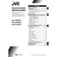
AV-21DMT3/AV-21D3 AV-2135TEE/AV-2135EE AV-21DMG3
SPECIFIC SERVICE INSTRUCTIONS
DISASSEMBLY PROCEDURE
REMOVING THE REAR COVER
1. Unplug the power plug. 2. As shown in figure, remove the
7
screws marked
!
and a
screw marked ". 3. Withdraw the rear cover toward you.
REMOVING THE MAIN PW BOARD
" After removing the rear cover. 1. Slightly raise the both sides of the MAIN PW BOARD by hand. 2. Withdraw the MAIN PW BOARD backward. (If necess ary, take off the wire clamp, c onnectors etc.)
REMOVING THE SPEAKER
" After removing the rear cover. 1. As shown in figure, remove the
2 screws marked # .
2. Follow the s ame steps when removing the other hand speak er.
CHECKING THE MAIN PW BOARD
1. To check the back side of the PW Board. 1) Pull out the MAIN PW Board. (Refer to REMOVING THE MAIN PW Board) 2) Erect the PW Board vertic ally so that you can easily check the back side of the PW Board. [CAUTION] " When erecting the PW Board, be careful s o that there will be no contacting with other PW Board. " Before turning on power, make sure that the CRT earth wire and other connector are properly c onnected.
WIRE CLAMPING AND CABLE TYING
1. Be sure to clamp the wire. 2. Never remove the c able tie used for tying the wires together. Should it be inadvertently removed, be sure to tie the wires with a new cable tie.
8
No. 52023
|
|
|
> |
|