|
|
|
Categories
|
|
Information
|
|
Featured Product
|
|
|
 |
|
|
There are currently no product reviews.
 ;
Very good expirience with owner-manuals.com.
5 Stars; In future if necessary, i´ll download manuals on this site.
;
Hi - happy with what I received but not quite what I wanted - my fault I assumed that service manual would also include operational instructions which is what I needed - all I needed to know was how to turn the radio - thanks
;
this Manual very important when i buy this Manual i already fix the trouble of my Camera..... thanks keep up the good work.!
 ;
This service manual helped me to repair my PIONEER. Iam very satisfied, that I found it here.
Even the price of manual was not so high that person would not be able to spend a few money.
But that is very worth spent money. Thanks
;
Excellent quality service manual. Quick processing, fair prices. Love to do business again. Thank you!!!
SECTION 3 DISASSEMBLY
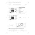
3.1 3.1.1 (1) (2) (3) DISASSEMBLY PROCEDURE REMOVING THE REAR COVER Unplug the power cord. Remove the 7 screws [A] as shown in the Fig. 1. Withdraw the REAR COVER toward you. 3.1.6 CHECKING THE PW BOARD � To check the back side of the PW Board. (1) Pull out the PW Board. (Refer to REMOVING THE MAIN PWB). (2) Erect the PW Board vertically so that you can easily check the back side of the PW Board.
3.1.2 REMOVING THE MAIN PWB � Remove the REAR COVER. (1) Slightly raise the both sides of the chassis by hand and withdraw the MAIN PWB backward. (If necessary, take off the wire clamp, connectors etc.)
3.1.3 REMOVING THE SPEAKER � Remove the REAR COVER. (1) Remove the 4 screws [B], and remove speaker as shown in Fig. 1. (2) Remove the speaker. (3) Remove the other side speaker by same procedure.
3.1.7 CAUTION � When erecting the PW Board, be careful so that there will be no contacting with other PW Board. � Before turning on power, make sure that the wire connector is properly connected. � When conducting a check with power supplied, be sure to confirm that the CRT EARTH WIRE (BRAIDED ASS'Y) is connected to the CRT SOCKET PW board.
3.1.4 REMOVING THE FRONT AV PWB � Remove the REAR COVER. � Remove the MAIN PWB. (1) Remove the 2 screws [C] as shown in Fig. 1. (2) Remove the FRONT AV PWB.
3.1.8 WIRE CLAMPING AND CABLE TYING (1) Be sure to clamp the wire. (2) Never remove the cable tie used for tying the wires together. Should it be inadvertently removed, be sure to tie the wires with a new cable tie.
3.1.5 REMOVING THE HEADPHONE PWB � Remove the REAR COVER. � Remove the MAIN PWB. (1) Remove the 1 screw [D] as shown in Fig. 1. (2) Remove the HEADPHONE PWB.
1-6 (No.52135)
|
|
|
> |
|