|
|
|
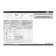
Categories
|
|
Information
|
|
Featured Product
|
|
|
 |
|
|
There are currently no product reviews.
 ;
It took about 24-hours after my payment before I was able to get to the download. Apparently, payment processing is not 100% automated. That is no big deal, just be aware of that going in.
After I got to it, it was in good shape, easy to read, etc. Not some cheap FAX copy looking thing.
Also, this site was the cheapest I found. Another Plus!
 ;
Good price, very legible manual, exactly what I needed -- but had to wait a day to actually get the download of the manual. Would have preferred to download it immediately after payment rather than waiting for someone to "process" my order. I was surprised that I had to wait that long.
;
As the only source for this manual it rather rank quite high since it is well scanned and perfectly readable.
;
the manual is in good quality and it's in pdf. manual was send in less then 24h.
regards
mike
;
I would not plug this machine in without finding a manual like this. In addition to setup and normal operating instructions, it has troubleshooting flowcharts, diagrammed mechanical adjustments, and schematics to beat the band. The tech I hand it to would be thrilled to find solder side PCB diagrams with component outlines superimposed, pinouts for every IC chip, and line drawings of transistors, with labeled legs.
As for printing quality, this may be a copy of a copy, but even the finest print when enlarged is very legible. There is a bit of grayed print over a few pages, as if a wet page were placed over it, but the print is still very legible. If you could borrow an original manual and get it printed and bound for 4 to 6 times the cost, you could get better quality. In that case you wouldn't be here. For price, utility, and availability I am rating this manual highly.
AV-21L31 AV-25L31
REMOVING THE CRT
* Replacement of the CRT should be performed by 2 or more persons.
CRT CHANGE TABLE
� After removing the rear cover, chassis etc.,
1. Putting the CRT change table on soft cloth, the CRT change table should also be covered with such soft cloth (shown in Fig. 2). 2. While keeping the surface of CRT down, mount the TV set on the CRT change table balanced will as shown in Fig. 3. 3. Remove 4 screws marked by arrows with a box type screwdriver as shown in Fig. 3. Since the cabinet will drop when screws have been removed, be sure to support the cabinet with hands. 4. After 4 screws have been removed, put the cabinet slowly on cloth (At this time, be carefully so as not to damage the front surface of the cabinet) shown in Fig. 4. The CRT should be assembled according to the opposite sequence of its dismounting steps.
APPROX. 35cm CLOTH
�
Fig. 2
�
CRT
* The CRT change table should preferably be smaller that the CRT surface, and its height be about 35cm.
CRT CHANGE TABLE BOX TYPE SCREW DRIVER
Fig. 3
CRT
COATING OF SILICON GREASE FOR ELECTRICAL INSULATION ON THE CRT ANODE CAP SECTION.
� Subsequent to replacement of the CRT and HV transformer or repair
of the anode cap, etc. by dismounting them, be sure to coat silicon grease for electrical insulation as shown in Fig. 5. 1. Wipe around the anode button with clean and dry cloth. (Fig. 5) 2. Coat silicon grease on the section around the anode button. At this time, take care so that any silicon greases does not sticks to the anode button. (Fig. 6) Silicon grease product No. KS - 650N
CABINET
CRT CHANGE TABLE
Fig. 4
CRT
Anode button
Approx. 20mm (Do not coat grease on this section
Silicon grease should be coated by 5mm or more from the outside diameter of anode cap.
Silicon grease coating
Anode button (No sticking of silicon grease)
Coating position of silicon grease Anode cap
Fig. 5
Fig. 6
8
No. 51908
|
|
|
> |
|