|
|
|
Categories
|
|
Information
|
|
Featured Product
|
|
|
 |
|
|
There are currently no product reviews.
 ;
Complete service and operation manual. All schematics are there, all circuit boards AND add-on boards. Including exploded views ,component names and specifications. Also electrical and mechanical adjustment procedures are in this manual. This manual also covers the more advanced BR-S811E unit. Scan quality is fair and usable.
 ;
High quality scan of original Service Manual. Everything´s fine!
;
Good scan of the original service manual. All schematics and adjustment procedures are there. It helped me to fix a long lasting problem with the tracking circuitry. The manual also includes the supplementals 1,2 and 3. Included are; electrical schematic's , pcb layout's, mechanical drawing's and exploded views, disassembly manual and maintenance procedures. 236 pages.
;
The Service Manual received was helpful. The electronic information is exactly what I needed.
I recomend all of my friends about this technical page.
;
High quality scan of service manual. I am satisfied!
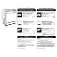
AV-21L81B AV-25L81B
REPLACEMENT OF CHIP COMPONENT
a CAUTIONS
1. 2. 3. 4. Avoid heating for more than 3 seconds. Do not rub the electrodes and the resist parts of the pattern. When removing a chip part, melt the solder adequately. Do not reuse a chip part after removing it.
a SOLDERING IRON
1. Use a high insulation soldering iron with a thin pointed end of it. 2. A 30w soldering iron is recommended for easily removing parts.
a REPLACEMENT STEPS
1. How to remove Chip parts
Resistors, capacitors, etc. (1) As shown in the figure, push the part with tweezers and alternately melt the solder at each end.
2. How to install Chip parts
Resistors, capacitors, etc. (1) Apply solder to the pattern as indicated in the figure.
(2) Grasp the chip part with tweezers and place it on the solder. Then heat and melt the solder at both ends of the chip part. (2) Shift with tweezers and remove the chip part.
Transistors, diodes, variable resistors, etc. (1) Apply extra solder to each lead.
Transistors, diodes, variable resistors, etc. (1) Apply solder to the pattern as indicated in the figure. (2) Grasp the chip part with tweezers and place it on the solder. (3) First solder lead A as indicated in the figure.
SOLDER
SOLDER
A B
(2) As shown in the figure, push the part with tweezers and alternately melt the solder at each lead. Shift and remove the chip part.
C
(4) Then solder leads B and C.
A B C
Note : After removing the part, remove remaining solder from the pattern.
No. 51903
13
|
|
|
> |
|