|
|
|
Categories
|
|
Information
|
|
Featured Product
|
|
|
 |
|
|
There are currently no product reviews.
 ;
Good quality, all schematics of few of models. There is also short form of user manual and regulation manual.
;
Perfect copy of the service manual. you can enlarge every page, and it comes up
with all details.
;
It´s very very nice manual with all, what i need. Original in good quality. Very fast business. Very much thanks...
;
Purchased the manual that I was looking for at a great price and could download it easily.. Great service experience and for future purchases I plan to use the site.
Thank you very much
;
Exactly what was needed to assess the product - excellent value and great service
AV-21LMT3 / AV-21LTR3 AV-21LT3 / AV-21LMG3 AV-2105EE
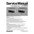
PURITY / CONVERGENCE ADJUSTMENT
PURITY ADJUSTMENT
1. Demagnetize CRT with the demagnetizer.
WEDGE
2. Loosen the retainer screw of the deflec tion yoke.
PURIT Y MAGNET (P)
3. Remove the wedges.
CRT
4. Input a green raster signal from the signal generator, and turn the screen to green raster.
DEFL ECTIO N YOKE
46
CRT SOCKET PWB
P / C MAGNET S
5. Move the deflection yoke backward. # P/C MAGNETS 6. Bring the long lug of the purity magnets on the short lug and position them horizontally. (Fig.2) P : PURITY MAGNET 4 : 4 POLES (convergence magnets) 6 : 6 POLES (convergence magnets) Fig.1
7. Adjust the gap between two lugs so that the GREEN RASTER will come into the c enter of the screen. (Fig.3)
8. Move the deflection yoke forward, and fix the pos ition of the deflection yoke so that the whole screen will bec ome green.
P RI YMG E U T A N TS
9. Ins ert the wedge to the top side of the deflection yoke so that it will not move.
10. Input a cross hatch signal.
S lug hort
11. Verify that the screen is horizontal.
Long ug l
12. Input red and blue raster signals, and make sure that purity is properly adjusted.
Bring t he long lug over th e short lu g and position them horizont ally.
Fig.2
(FRONT VIEW)
GREEN RASTER
CENTER
Fig.3
No. 52030
29
|
|
|
> |
|