|
|
|
Categories
|
|
Information
|
|
Featured Product
|
|
|
 |
|
|
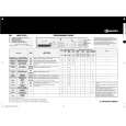
There are currently no product reviews.
 ;
fast and easy and exactly what I was looking for. Not the cheapest but value for money after all.
;
The manual for the Sansui P-L75 was not one of the more informative turntable manuals around but for $5 it was helpful enough.
;
VERY GOOD SERVICE.FAST ANS VERY HONEST PRICE .RHAANK HERNAN
 ;
Thanks to this service manual I repaired my old camcorder! The manual perfectly explains how to disassemble the camcorder step by step.
;
This manual is very useful because it presents the technical specifications of the cd player, including the manufacturer of the reader, this helps if you need to replace it. It also displays the settings and layout of the circuit.
AV-21LMT3 / AV-21LTR3 AV-21LT3 / AV-21LMG3 AV-2105EE
PURITY / CONVERGENCE ADJUSTMENT
PURITY ADJUSTMENT
1. Demagnetize CRT with the demagnetizer.
WEDGE
2. Loosen the retainer screw of the deflec tion yoke.
PURIT Y MAGNET (P)
3. Remove the wedges.
CRT
4. Input a green raster signal from the signal generator, and turn the screen to green raster.
DEFL ECTIO N YOKE
46
CRT SOCKET PWB
P / C MAGNET S
5. Move the deflection yoke backward. # P/C MAGNETS 6. Bring the long lug of the purity magnets on the short lug and position them horizontally. (Fig.2) P : PURITY MAGNET 4 : 4 POLES (convergence magnets) 6 : 6 POLES (convergence magnets) Fig.1
7. Adjust the gap between two lugs so that the GREEN RASTER will come into the c enter of the screen. (Fig.3)
8. Move the deflection yoke forward, and fix the pos ition of the deflection yoke so that the whole screen will bec ome green.
P RI YMG E U T A N TS
9. Ins ert the wedge to the top side of the deflection yoke so that it will not move.
10. Input a cross hatch signal.
S lug hort
11. Verify that the screen is horizontal.
Long ug l
12. Input red and blue raster signals, and make sure that purity is properly adjusted.
Bring t he long lug over th e short lu g and position them horizont ally.
Fig.2
(FRONT VIEW)
GREEN RASTER
CENTER
Fig.3
No. 52030
29
|
|
|
> |
|