|
|
|
Categories
|
|
Information
|
|
Featured Product
|
|
|
 |
|
|
There are currently no product reviews.
 ;
The purchased manual is an high quality scan of the original Philips paper-based Service Manual. I am very satisfied!
 ;
The purchased manual is an scan of the original Panasonic paper-based Service Manual. Unfortunately the contrast is not perfect, but I am satisfied anyway!
;
The purchased manual is an high-quality scan of the original JVC paper-based Service Manual. The Service Manual includes the Owner´s Manual, so you do not have to buy both of them.
;
It paid to find this Service Manual, couldn't find it anywhere else. Exactly what I wanted. Received within 24 hours.
;
Complete manual with clear schematic diagrams and printed circuit board layouts of two variants of the headset and the transmitter an old and a new version.
Also shows how the headset and the transmitter is opened and how transmitter and receivers can be adjusted and where to measure.
I had no problems to repair the headset using this service manual.
AV-21LMT3 / AV-21LTR3 AV-21LT3 / AV-21LMG3 AV-2105EE
PURITY / CONVERGENCE ADJUSTMENT
PURITY ADJUSTMENT
1. Demagnetize CRT with the demagnetizer.
WEDGE
2. Loosen the retainer screw of the deflec tion yoke.
PURIT Y MAGNET (P)
3. Remove the wedges.
CRT
4. Input a green raster signal from the signal generator, and turn the screen to green raster.
DEFL ECTIO N YOKE
46
CRT SOCKET PWB
P / C MAGNET S
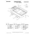
5. Move the deflection yoke backward. # P/C MAGNETS 6. Bring the long lug of the purity magnets on the short lug and position them horizontally. (Fig.2) P : PURITY MAGNET 4 : 4 POLES (convergence magnets) 6 : 6 POLES (convergence magnets) Fig.1
7. Adjust the gap between two lugs so that the GREEN RASTER will come into the c enter of the screen. (Fig.3)
8. Move the deflection yoke forward, and fix the pos ition of the deflection yoke so that the whole screen will bec ome green.
P RI YMG E U T A N TS
9. Ins ert the wedge to the top side of the deflection yoke so that it will not move.
10. Input a cross hatch signal.
S lug hort
11. Verify that the screen is horizontal.
Long ug l
12. Input red and blue raster signals, and make sure that purity is properly adjusted.
Bring t he long lug over th e short lu g and position them horizont ally.
Fig.2
(FRONT VIEW)
GREEN RASTER
CENTER
Fig.3
No. 52030
29
|
|
|
> |
|