|
|
|
Categories
|
|
Information
|
|
Featured Product
|
|
|
 |
|
|
There are currently no product reviews.
 ;
Superb rendition. Drawings (schematics) complete and unabridged. I do a great deal of vintage audio restoration. Documentation is essential for successful repairs. I have found sources over the years that offer good documentation, but rarely all that is necessary. Owner's Manuals has filled that void with complete and legible documentation. They have narrowed my "favorites" to a more manageable collection. This Denon manual in particular contained the latest revisions level, and offered alterations favorable to updating the item. The Illustrated Parts Breakdown (IPB) was well enough detailed to simplify part symbols and physical locations. You will not be disappointed!
;
Clear and concise. Saved me a lot of time and money.
;
Superb manual. Exactly what I ordered and made available in a very timely manner.
 ;
very fast detailed and accurate hope to do business again
;
This was precisely what I was looking for. Complete and good quality!
SECTION 3 DISASSEMBLY
3.1 DISASSEMBLY PROCEDURE 3.1.1 REMOVING THE TWIN PORT BASS BLASTER UNIT [AV-21VT31/P] � Unplug the power supply cord. (1) Disconnect the TWIN PORT BASS BLASTER UNIT's cord from the rear of the TV set. (2) Remove the TWIN PORT BASS BLASTER UNIT by pulling it upwards. NOTE: After removing the TWIN PORT BASS BLASTER UNIT, proceed to the following procedure. 3.1.2 REMOVING THE REAR COVER
� Unplug the power cord.
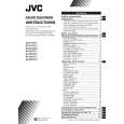
(1) Remove the 9 screws [A] and 4 screws [B] as shown in Fig.1. (2) Withdraw the REAR COVER toward you. CAUTION: When reinstalling the rear cover, carefully push it inward after inserting the MAIN PWB into the REAR COVER groove. 3.1.3 REMOVING THE MAIN PW BOARD
� Remove the REAR COVER.
(1) Slightly raise the both sides of the MAIN PWB by hand and remove the PB stopper [D] from the front cabinet. (2) Withdraw the MAIN PWB backward. (If necessary, take off the wire clamp and connectors, etc.)
3.1.4 REMOVING THE SPEAKER
� Remove the REAR COVER.
(1) Remove the 2 screws [C] as shown in Fig.1. (2) Follow the same steps when removing the other hand SPEAKER.
3.1.5 CHECKING THE MAIN PW BOARD � To check the back side of the MAIN PWB. (1) Pull out the MAIN PWB. (Refer to REMOVING THE MAIN PW BOARD). (2) Erect the MAIN PWB vertically so that you can easily check its back side. CAUTIONS: � Before turning on power, make sure that the CRT earth wire and other connectors are properly connected. � When repairing, connect the DEG. COIL to the DEG. connector on the MAIN PWB. 3.1.6 WIRE CLAMPING AND CABLE TYING (1) Be sure to clamp the wire. (2) Never remove the cable tie used for tying the wires together. Should it be inadvertently removed, be sure to tie the wires with a new cable tie.
(No. 52180) 1-7
|
|
|
> |
|