|
|
|
Categories
|
|
Information
|
|
Featured Product
|
|
|
 |
|
|
There are currently no product reviews.
 ;
Great tape deck manual!
I'm very positively surprised, because it is a very long manual, lot of pages, drawings, diagrams, description of how to make the alignment and adjustment procedures.
It is as good as the old "Naka" manuals from the 1970's - if somebody have seen them, they know what I mean by that.
I recommend to buy this very much !
;
I am a vintage hifi collector. No way to fix that device without the appropriate service manual...thanks to your site I got it and every thing is easier now. I got the manual right after ordering: fast cheap accurate ... thank you
;
Wonderful job clear. Qick fantastic. These people are really good. If even a problem arise they are wonderful assisting you. These scheme is so net despite this is a very old TV. Thank you for everything!!!!!!!!
;
Detailed schematic diagram, manual for professionals
;
Good service manual,exploded view,adjusment and test point locations,head alignment,mechanical checks and adjusments,all perfect.
AV-25K83
SPECIFIC SERVICE INSTRUCTIONS
DISASSEMBLY PROCEDURE
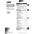
REMOVING THE REAR COVER
1. Unplug the power supply cord. 2. Remove the 7 screws marked � and 4 screws marked ı as shown in Fig.1. 3. Withdraw the Rear cover toward you. [CAUTION] When reinstalling the rear cover, carefully push it inward after inserting the Main PWB into the rear cover groove.
WIRE CLAMPING AND CABLE TYING
1. Be sure to clamp the wire. 2. Never remove the cable tie used for tying the wires together. Should it be inadvertently removed, be sure to tie the wires with a new cable tie.
�
REMOVING THE CHASSIS (CHASSIS BASE AND CONTROL BASE)
� After removing the rear cover.
1. Slightly raise the both sides of the chassis by hand and remove the 2 claws marked � under the chassis from the front cabinet as shown in Fig.1. 2. Withdraw the chassis backward. (If necessary, take off the wire clamp, connector�s etc.)
* When conducting a check with power supplied, be sure to confirm
that the CRT earth wire is connected to the CRT SOCKET PWB and the Main PWB.
REMOVING THE CONTROL BASE
� After removing the rear cover and the chassis.
1. While pushing down the 2 claws marked � as shown in Fig. 2 and pull out the Control base in the direction of arrow marked ´ as shown in Fig. 2, the control base can be removed. (If necessary, take off the wire, connector�s etc.)
REMOVING THE SPEAKER
� After removing the rear cover.
1. Remove the 4 screws marked � as shown in Fig.1. 2. Withdraw the speaker backward. 3. Follow the same steps when removing the other hand speaker.
CHECKING THE MAIN PW BOARD
1. To check the back side of the Main PWB. 1) Pull out the chassis. (Refer to REMOVING THE CHASSIS). 2) Erect the chassis vertically so that you can easily check the back side of the Main PWB. [CAUTION] When erecting the chassis, be careful so that there will be no contacting with other PW Board. Before turning on power, make sure that the CRT earth wire and other connectors are properly connected. When repairing, connect the Deg. coil to the DEG. connector on the Main PWB.
� � �
6
No. 52077
|
|
|
> |
|