|
|
|
Categories
|
|
Information
|
|
Featured Product
|
|
|
 |
|
|
There are currently no product reviews.
 ;
The schematic is very helpful and the images are very good.The schematic is very helpful and the images are very good.The schematic is very helpful and the images are very good.The schematic is very helpful and the images are very good.The schematic is very helpful and the images are very good.The schematic is very helpful and the images are very good.
;
Welcome. The scheme is clearly helped me to repair. Worth to download it.
 ;
Excellent manual, very clear, technical specification provided, useful information regarding adjustment and set up.
;
fast and easy and exactly what I was looking for. Not the cheapest but value for money after all.
;
The manual for the Sansui P-L75 was not one of the more informative turntable manuals around but for $5 it was helpful enough.
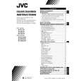
AV-29L81B
DISASSEMBLY PROCEDURE [AV-29L81B-BK]
REMOVING THE REAR COVER
1. Unplug the AC power cord. 2. Remove the 16 screws marked � as shown in Fig. 2. 3. Withdraw the Rear cover toward you. [CAUTION] When reinstalling the rear cover, carefully push it inward after inserting the Main PWB into the rear cover groove.
CHECKING THE MAIN PW BOARD
1. To check the back side of the Main PWB. 1) Pull out the chassis. (Refer to REMOVING THE CHASSIS). 2) Erect the chassis vertically so that you can easily check the back side of the Main PWB. [CAUTION] When erecting the chassis, be careful so that there will be no contacting with other PW Board. Before turning on power, make sure that the CRT earth wire and other connectors are properly connected. When repairing, connect the Deg. coil to the DEG. connector on the Main PWB.
�
REMOVING THE CHASSIS (CHASSIS BASE AND CONTROL BASE)
� � �
� After removing the rear cover.
1. Slightly raise the both sides of the chassis by hand and remove the 2 claws marked ı under the chassis from the front cabinet as shown in Fig. 2. 2. Withdraw the chassis backward. (If necessary, take off the wire clamp, connector�s etc.)
WIRE CLAMPING AND CABLE TYING
1. Be sure to clamp the wire. 2. Never remove the cable tie used for tying the wires together. Should it be inadvertently removed, be sure to tie the wires with a new cable tie.
* When conducting a check with power supplied, be sure to confirm
that the CRT earth wire is connected to the CRT SOCKET PWB and the Main PWB.
REMOVING THE AV TERMINAL BOARD
� After removing the rear cover.
1. Remove the 4 screws marked � as shown in Fig. 2. 2. When you pull out the AV Terminal board in the direction of arrow marked � as shown in Fig. 2, it can be removed.
REMOVING THE CONTROL BASE
� After removing the rear cover and the chassis.
1. While pushing down the 2 claws maked ´ as shown in Fig. 3. 2. When you pull out the Control base in the direction of arrow maked � as shown in Fig. 3. (If necessary, take off the wire, connector�s etc.)
REMOVING THE DOME SPEAKER BOX
� After removing the rear cover.
1. Remove the lower side screw marked � � � first, and then the upper side screw as shown in Fig. 2. 2. Follow the same step for removing the other hand speaker box.
8
No. 51853
|
|
|
> |
|