|
|
|
Categories
|
|
Information
|
|
Featured Product
|
|
|
 |
|
|
There are currently no product reviews.
 ;
This site is working fine! Did buy a manual for SX-EX25L and after a while I could download it and fix the problem. Nice and easy!
 ;
Complete manual as pdf-file in very good quality. Very helpful and fast availability.
;
Complete service manual in very good scanning quality with all schematic and PWB graphics as well as assembly & maintenance instructions. A slight drawback is that the rastering of the PWB graphics sometimes makes it a bit difficult to follow fine traces, but no showstopper.
;
Purchased the manual that I was looking for at a great price and could download it easily.. Great service experience and for future purchases I plan to use the site. Thank you very much
;
Service manual in good quality, it was very helpful to me. Perfect service, I am very satisfied.
Jochen Kelm
AV-29L81
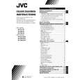
DISASSEMBLY PROCEDURE [AV-29L81-BK]
REMOVING THE REAR COVER
1. Unplug the AC power cord. 2. Remove the 16 screws marked � as shown in Fig.2. 3. Withdraw the Rear cover toward you. [CAUTION] When reinstalling the rear cover, carefully push it inward after inserting the Main PWB into the rear cover groove.
CHECKING THE MAIN PW BOARD
1. To check the back side of the Main PWB. 1) Pull out the chassis. (Refer to REMOVING THE CHASSIS). 2) Erect the chassis vertically so that you can easily check the back side of the Main PWB. [CAUTION] When erecting the chassis, be careful so that there will be no contacting with other PW Board. Before turning on power, make sure that the CRT earth wire and other connectors are properly connected. When repairing, connect the Deg. coil to the DEG. connector on the Main PWB.
�
REMOVING THE CHASSIS (CHASSIS BASE AND CONTROL BASE)
� � �
� After removing the rear cover.
1. Slightly raise the both sides of the chassis by hand and remove the 2 claws marked ı under the chassis from the front cabinet as shown in Fig.2. 2. Withdraw the chassis backward. (If necessary, take off the wire clamp, connector�s etc.)
WIRE CLAMPING AND CABLE TYING
1. Be sure to clamp the wire. 2. Never remove the cable tie used for tying the wires together. Should it be inadvertently removed, be sure to tie the wires with a new cable tie.
* When conducting a check with power supplied, be sure to confirm
that the CRT earth wire is connected to the CRT Socket PWB and the Main PWB.
REMOVING THE AV TERMINAL BOARD
� After removing the rear cover.
1. Remove the 4 screws marked � as shown in Fig.2. 2. When you pull out the AV Terminal board in the direction of arrow marked � as shown in Fig.2, it can be removed.
REMOVING THE CONTROL BASE
� After removing the rear cover and the chassis.
1. While pushing down the 2 claws maked ´ as shown in Fig. 3. 2. When you pull out the Control base in the direction of arrow maked � as shown in Fig. 3. (If necessary, take off the wire, connector�s etc.)
REMOVING THE SPEAKER
� After removing the rear cover.
1. Remove the 4 screws marked � as shown in Fig.2. 2. Withdraw the speaker backward. 3. Follow the same steps when removing the other hand speaker.
8
No. 51840
|
|
|
> |
|