|
|
|
Categories
|
|
Information
|
|
Featured Product
|
|
|
 |
|
|
There are currently no product reviews.
 ;
very good manual as always. easy to read, detailed and includes schematic
;
I'm very satisfied with your manual service. Your website made it easy to locate the correct manual. Also the quality is great and I never had a problem reading the fine details.
Thanks again.
Jeff Miller
JM Electronics
 ;
Good quality service manual German user manual. German user manual This is a quality scan of a manual in excellent condition and is just as good as having the original manual in hand
;
The manual for Sony LBT-D505 component stereo system is was excellent , with schematics, parts layout and parts list as well as instructions for adjustments for each component. Print was clear even when enlarged.
;
It's exactly a complete and very useful manual with all details what I needed. Thank you!I will come back whenever I need your manuals or schematics.
AV-21LXB AV-25LXB
SPECIFIC SERVICE INSTRUCTIONS
DISASSEMBLY PROCEDURE
REMOVING THE TWIN PORT BASS BLASTER UNIT
1. Unplug the AC power cord. 2. Disconnect the Twin Port Bass Blaster Unit's cord from the rear of the TV set. 3. Remove the Twin Port Bass Blaster Unit by pulling it upward.
REMOVING THE REAR COVER
� After removing the twin port bass blaster unit.
1. Remove the 7 or 9 screws marked � and 4 screws maked shown in Fig.1. 2. Withdraw the Rear cover toward you.
ı as
[CAUTION] When reinstalling the rear cover, carefully push it inward after inserting the Main PWB into the rear cover groove.
�
REMOVING THE MAIN PW BOARD
� After removing the rear cover.
1. Slightly raise the both sides of the Main PWB by hand, take off the PB Stopper marked � from the front cabinet. 2. Withdraw the Main PWB backward. (If necessary, take off the wire clamp and connectors, etc.)
REMOVING THE SPEAKER
� After removing the rear cover.
1. Remove the 2 screws marked � and 2 screws maked ´ as shown in Fig.1. 2. Follow the same steps when removing the other hand speaker.
CHECKING THE MAIN PW BOARD
1. To check the back side of the Main PWB. 1) Pull out the Main PWB. (Refer to REMOVING THE MAIN PW BOARD). 2) Erect the Main PWB vertically so that you can easily check its back side. [CAUTION] Before turning on power, make sure that the CRT earth wire and other connectors are properly connected. When repairing, connect the Deg. coil to the DEG. connector on the Main PWB.
� �
WIRE CLAMPING AND CABLE TYING
1. Be sure to clamp the wire. 2. Never remove the cable tie used for tying the wires together. Should it be inadvertently removed, be sure to tie the wires with a new cable tie.
6
No. 51850
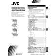 $4.99 AV-25LXB JVC
Owner's Manual Complete owner's manual in digital format. The manual will be available for download as PDF file aft…
|
|
|
> |
|