|
|
|
Categories
|
|
Information
|
|
Featured Product
|
|
|
 |
|
|
There are currently no product reviews.
 ;
We received the manual in a timely manner and it was exactly what we were expecting. Excellent replacement for original Service Manual.
All schematics are very legible. We are really satisfied.
;
We received the manual in a timely manner and it was exactly what we were expecting. Excellent replacement for original Service Manual.
All schematics are very legible. We are really satisfied.
;
We received the manual in a timely manner and it was exactly what we were expecting. Excellent replacement for original Service Manual.
All schematics are very legible. We are really satisfied.
;
We received the manual in a timely manner and it was exactly what we were expecting. Excellent replacement for original Service Manual.
All schematics are very legible. We are really satisfied.
;
We received the manual in a timely manner and it was exactly what we were expecting. Excellent replacement for original Service Manual.
All schematics are very legible. We are really satisfied.
AV-27D303 AV-27D203
SPECIFIC SERVICE INSTRUCTIONS
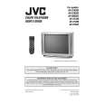
DISASSEMBLY PROCEDURE
REMOVING THE REAR COVER
1. Disc onnect the power plug from wall outlet. 2. As s hown in the Fig.1, remove the 11 screws marked ! . 3. As s hown in Fig.1, remove the
CHECKING THE PW BOARD
To check the PW Board from back side. 1. Pull out the chassis (refer to REMOVING THE MAIN PWB). 2. Erect the chas sis vertically so that you c an easily check the bac k side of the PW Board.
4 screws marked ".
4. Then remove the REAR COVER toward you.
REMOVING THE MAIN PWB
" After removing the REAR COVER. 1. Pick this side of the MAIN PWB and raise one slightly, take off the PWB stopper marked # from the c abinet bottom. 2. Withdraw the chass is backward. (If necess ary, remove the wire clamp, c onnectors etc.)
CAUTION
" When erecting the chassis, be careful so that there will be no contacting with other PW Board. " Before turning on power, make s ure that the wire connec tor is properly connec ted. " When conducting a check with power supplied, be sure to confirm that the CRT EART H WIRE (BRAIDED ASS� Y) is � connected to the CRT SOCKET PW boar d.
REMOVING THE SPEAKER
" After removing the rear cover. 1. As shown in Fig. 1, removing the screws marked
WIRE CLAMPING AND CABLE TYING
$,
then
1. Be sure to clamp the wire. 2. Never remove the c able tie used for tying the wires together. Should it be inadvertently removed, be sure to tie the wires with a new cable tie.
remove the speaker. 2. Follow the s ame steps when removing the other hand speak er. NOTE : When removing the screws marked of the speak er, remove the lower side screw first, and then remove the upper one.
$
8
No.51940
|
|
|
> |
|