|
|
|
Categories
|
|
Information
|
|
Featured Product
|
|
|
 |
|
|
There are currently no product reviews.
 ;
Well.. I'd searched for this manual and although I found many copies online I was pleased to find your website with a well balanced pricing system and easy to search and follow links. That together with the very quick response time was just what I was looking for.. being a very impatient tech.. ;-) I had the service manual in front of me within a short time.
Bookmarked.. and you can bet I will always come here first for my service & user manuals..
best regards
Ed(Tony) Foley
G7WHK
;
I will definitely be back for more information when I need it.
;
The service manual when downloaded and printed out was clear and easy to read. I would have liked to have been able to enlarge some details, but this was not possible as the file permissions did not allow this. The service was very good. The time taken from placing my order to downloading the document was only a few minutes.
 ;
The manual is useful for trouble shooting for an old instrument. It saved money,and let me enjoy DIY.
;
Perfect source of information for replacing the HDD and performing general diagnostics.
AV-27D104 AV-27D304 AV-27430 AV-27432 2.5 DISASSEMBLY PROCEDURE 2.5.1 REMOVING THE REAR COVER [AV-27D104 / AV-27D304] (1) Unplug the power plug. (2) Remove the 11 screws [A] (Fig.1). (3) Remove the 4 screws [B] (Fig.1). (4) Then remove the REAR COVER toward you. 2.5.2 REMOVING THE REAR COVER [AV-27430 / AV-27432] (1) Unplug the power plug. (2) Remove the 7 screws [A] (Fig.2). (3) Remove the 4 screws [B] (Fig.2). (4) Then remove the REAR COVER toward you. 2.5.6 CHECKING THE PW BOARD (1) Pull out the MAIN PWB (refer to REMOVING THE MAIN PWB). (2) Erect the MAIN PWB vertically so that you can easily check the backside of the PW Board. CAUTION: � When erecting the chassis, be careful so that there will be no contacting with other PW Board. � Before turning on power, make sure that the wire connector is properly connected. � When conducting a check with power supplied, be sure to confirm that the CRT EARTH WIRE (BRAIDED ASS'Y) is connected to the CRT SOCKET PW board.
2.5.3 REMOVING THE MAIN PWB � Remove the REAR COVER. (1) Raise this side of the MAIN PWB, and remove the PWB STOPPER [C] from the cabinet. (2) Withdraw the MAIN PWB backward. (If necessary, remove the wire clamp, connectors etc.)
2.5.7 WIRE CLAMPING AND CABLE TYING (1) Be sure to clamp the wire. (2) Never remove the cable tie used for tying the wires together. Should it be inadvertently removed, be sure to tie the wires with a new cable tie.
2.5.4 REMOVING THE SPEAKER [AV-27D104 / AV-27D304] � Remove the REAR COVER. (1) Remove the 4 screws [D], then remove the speaker (Fig.1). (2) Follow the same steps when remove the other hand speaker.
2.5.5 REMOVING THE SPEAKER [AV-27430 / AV-27432] � Remove the REAR COVER. (1) Remove the 2 screws [D], then remove the speaker (Fig.2). (2) Follow the same steps when remove the other hand speaker. NOTE: When removing the 2 screws [D] of the speaker, remove the lower side screw first, and then remove the upper one.
1-6 (No.52102)
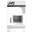 $4.99 AV27D304 JVC
Owner's Manual Complete owner's manual in digital format. The manual will be available for download as PDF file aft… 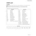 $4.99 AV-27D304 JVC
Parts Catalog Parts Catalog only. It's available in PDF format. Useful, if Your equipment is broken and You need t…
|
|
|
> |
|