|
|
|
Categories
|
|
Information
|
|
Featured Product
|
|
|
 |
|
|
There are currently no product reviews.
 ;
Great service! I got manual to my sony receiver for very reasonoble price.
;
Good service, well organized. Cheap, and the service manual was as expected. A valuable service for those of us wanting to keep the old junk going!
;
The manual arrived very quickly and had all the information I needed - Very satisfied with this seller. - Thanks -
;
Good quality, the manual help me to repair the echo/reverb section
;
A good service manual with lots of info and a very fair price
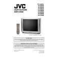
AV-27D503
SPECIFIC SERVICE INSTRUCTIONS
DISASSEMBLY PROCEDURE
REMOVE THE REAR COVER
" Unplug the power plug. 1. Remove the 12 screws marked ! "as shown in Fig.2. 2. Remove the rear c over toward you. * When reinstalling the rear cover, c arefully push it inward after inserting the chassis into the rear c over groove.
REMOVING THE SPEAKER
" After removing the rear cover and chassis. 1. Remove the 4 screws marked *" *"(Fig.2.) 2. Follow the s ame steps when removing the other hand speaker.
CHECKING THE MAIN PW BOARD
1. To check the backs ide of the MAIN PW Board. (1) Pull out the chassis . (Refer to REMOVING THE CHASSIS). (2) Erect the chassis vertically so that you can easily check the backside of the MAIN PW Board. [CAUTION] � � When erecting the chassis, be careful so that there will be no contacting with other PWB. Before turning on power, make sure that the CRT earth wire and other connectors are properly connected.
REMOVING THE CHASSIS
" After removing the rear cover. the 2 claws marked # (Fig.1 and Fig.2) under the both sides of the chassis from the front cabinet. 2. Draw the chassis backward along the rail marked the arrow direc tion marked %(Fig.2.). 1. Slightly raise the both sides of the c hassis by hand and remov e
$ (Fig.1)
in
(If necess ary, take off the wire clamp, c onnector�s etc.) * When c onducting a chec k with power supplied, be sure to confirm that the CRT earth wire is c onnected to the CRT SOCKET PWB and the MAIN PWB.
WIRE CLAMPING AND CABLE TYING
1. Be sure to clamp the wire. 2. Never remove the c able tie used for tying the wires together. Should it be inadvertently removed, be sure to tie the wires with a new c able tie. FRONT CABINET CHASSIS MAIN PWB
REMOVING THE TERMINAL BOARD
" After removing the rear cover. 1. Remove the 4 screws marked"& (Fig.2) "' . 2. When you pull out the TERMINAL BOARD, it can be removed.
REMOVING THE FRONT CONTROL PW BOARD
" After removing the rear cover and chassis.
C
1. Remove the 2 screws marked ( (Fig.2). 2. Then remove the FRONT CONTROL PWB.
REMOVING THE FRONT AV IN PW BOARD
" After removing the rear cover and chassis. 1. Remove the 2 screws marked ) (Fig.2.). 2. Then remove the FRONT AV IN PW B.
B
Fig. 1
6
No. 51946
|
|
|
> |
|