|
|
|
Categories
|
|
Information
|
|
Featured Product
|
|
|
 |
|
|
There are currently no product reviews.
 ;
I received a good service manual, with good resolution. Improve the instructions for the purchase because they are not well understood.
For the rest, so good.
Thanks Angel.
;
Very good documentation for the Grundig 2077 model (as well as similar 800/900/1000 series radios). The first two pages are a summary of reception specifications and output capability. The third page is the tuner dial indicator and dial cord routing diagram. the final ~5 pages are the schematics for the various models (including 2077). The scan quality of the schematics are good, adn can be easily read if zoomed in. The documents are in German, not English as stated. It would have been nice to have the tuning sequence and settings, and some trouble shooting materials... or component and wiring map.
 ;
Perfect like it was descriped, Perfect like it was descriped
;
Very good detail, all pages clear, exactly what I needed
;
Excellent service, and just what I needed to service my TU-7700. All pages of the manual are clear and easily readable.
AV-27F802
SPECIFIC SERVICE INSTRUCTIONS
DISASSEMBLY PROCEDURE
REMOVING THE REAR COVER
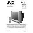
1. Unplug the power supply cord. 2. Remove the 12 screws marked A as shown in Fig.1. 3. Withdraw the REAR COVER toward you. [CAUTION]
REMOVING THE DAF PW BOARD
� After removing the rear cover and chassis.
1. Lift the right side of the DAF PWB while pressing the PWB stopper marked J and claw marked K in the arrow direction marked L as shown in Fig.1. 2. Then remove the DAF PWB. (If necessary, take off the wire, connector�s etc.)
� When reinstalling the rear cover, carefully push it inward after inserting the MAIN PWB into the rear cover groove.
REMOVING THE SPEAKER REMOVING THE CHASSIS
� After removing the rear cover.
1. Remove the 2 screws marked M as shown in Fig.1. 2. Withdraw the speaker backward. 3. Follow the same steps when removing the other hand speaker.
� After removing the rear cover.
1. Slightly raise the both sides of the chassis by hand and remove the 3 claws marked B under the chassis from the front cabinet as shown in Fig.1. 2. Withdraw the chassis backward along the rail in the arrow direction marked C as shown in Fig.1. (If necessary, take off the wire clamp, connector�s etc.)
CHECKING THE MAIN PW BOARD
1. To check the back side of the MAIN PW Board. 1) Pull out the chassis. (Refer to REMOVING THE CHASSIS). 2) Erect the chassis vertically so that you can easily check the back side of the MAIN PW Board. [CAUTION] When erecting the chassis, be careful so that there will be no contacting with other PW Board. other connectors are properly connected.
* When conducting a check with power supplied, be sure to confirm that the CRT earth wire is connected to the CRT SOCKET PWB and the MAIN PWB.
REMOVING THE TERMINAL BOARD
� After removing the rear cover.
1. Remove the 6 screws marked D as shown in Fig.1. 2. When you pull out the TERMINAL BOARD in the direction of arrow marked E as shown in Fig.1, it can be removed.
� � Before turning on power, make sure that the CRT earth wire and
WIRE CLAMPING AND CABLE TYING REMOVING THE FRONT AND POWER SW PW BOARDS
1. Be sure clamp the wire. 2. Never remove the cable tie used for tying the wires together. Should it be inadvertently removed, be sure to tie the wires with a new cable tie.
� After removing the rear cover and chassis.
1. Remove the 6 screws marked F as shown in Fig.1. 2. Then remove the FRONT PWB and POWER SW PWB. (If necessary, take off the wire, connector�s etc.)
REMOVING THE LF PW BOARD
� After removing the rear cover and chassis.
1. Lift the left side of the LF PWB while pressing the 2 PWB stoppers marked G in the arrow direction marked H as shown in Fig.1. 2. Then remove the LF PWB. (If necessary, take off the wire, connector�s etc.)
6
No. 51757
|
|
|
> |
|