|
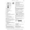
There are currently no product reviews.
 ;
VERY NICE FOR COURTESY AND PRECISION!.
tHE SITE IS VERY IMPORTANT FOR ALL DEVICES
vERY GOOD
;
+++ Is is fine, that was what i looking for. Thanks! +++
;
A very good complete archive, i am very satisfied for document.
 ;
The Service Manual received was helpful. The electronic information is exactly what I needed.
;
The Manual was perfect.
The deliverie was perfect.
Thanks
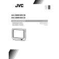
AV-28BK5ECB AV-28BK5ECS CHASSIS DESCRIPTION
[Digital Scan Operation]
100Hz Digital Scan Converter circuit 100Hz converter circuit consists of the following ICs. - TC90A36F, IC7201 Field Progressive Converter - MSM518221A, IC7202, IC7203 Video Memory - TLC2932I, IC7204, IC7205 PLL (Phase Locked Loop) - MC74HC04AFP, IC7341 invertor The Y-signal output from IC101 is sent to pin 85 of IC7201<TC90A36F>, field progressive converter, after controlling the amplitude level and band-pass limiting by the circuit consist of Q7301, Q7302, Q7303, Q7304 and 8MHz LPF. The U/V-signal are also controlling the amplitude level and band-pass limiting by the circuit consist of Q7311, Q7312, Q7313, Q7314, Q7321, Q7322, Q7323, Q7324 and 4MHz LPF respectively. The U-signal is sent to pin 90 of IC7201and the V-signal is sent to pin 92 of IC7201. The HD signal is sent to pin 63 of IC7201 with positive polarity through IC7341 for shaping the waveform. The VD-signal is sent to pin68 of IC7201 with negative polarity through IC7341. The Y-signal input to IC7201 is converted from A to D in 8bit and output from pins 31 to 50 of IC7201 to pins 1 to 4 and 24 to 27 of IC7203<MSM51822A>, video memory, for writing. Digital scan circuit
LPF Q7351-Q7354 LPF Q7361-Q7364 LPF Q7371-Q7374
IC7203 IC7202
6 9 | 31
2Y 2U 2V
98
100
IC7201 DOUBLE SCAN CONVERTER <TC90A36F>
31 | 50
92
LPF Q7321-Q7324 LPF Q7311-Q7314 LPF Q7301-Q7304
V U
90
Video Memory
85 53 59 63 68 70 71
Y
IC7204 PLL <READ>
9 4
IC7341 Inverter
13 12 11 10
2HD 2VD VD HD
IC7205 PLL <WRITE>
5 4
6 4
5 1
Fig.-6
6
No. 51758
|