|
|
|
Categories
|
|
Information
|
|
Featured Product
|
|
|
 |
|
|
There are currently no product reviews.
 ;
Very fast, clear and usefull site !
Also this Service Manual are very well maked and with a very good definition !
Very fast download speed !
Recomended Seller !
;
The manual you sent me was excellent. It included clear, readable diagrams and a usable parts list. I would surely use your service again. Thanks
;
Payments were processed quickly and items were exactly as described. I will use owner-manuals.com in the future for any other manual needs.
;
The Technics manual was very clear and I was able to solve my technical problems.
I did not think that anyone kept these manuals and was pleasantly surprised to find them on the Internet and at an affordable price.
I would recommend Owner Manuals as a first source of technical products for ‘dated’ equipment manuals.
Ian
;
The content of the manual was not found on the Internet and was a hard find. I check the net for 5 hours until I came across this web-site. When I did find the book it Auto loaded into my IPAD PDF shelf for books for review at anytime. Overall I am satisfied with the book and it answered all my questions. This repair book is obsolete because the product I bout it for is pretty old. Thanks for the help with the download and even having the manual. Thanks 73's K5HRD
AV-28BT8ENS / AV-28BT8ENB / AV-28BT80EN AV-28BT8EPS / AV-28BT8EPB / AV-28BT80EP AV-28BT8EES / AV-28BT8EEB/ AV-28BS88EN
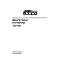
REPLACEMENT OF CHIP COMPONENT
! CAUTIONS
1. 2. 3. 4. Avoid heating for more than 3 seconds. Do not rub the electrodes and the resist parts of the pattern. When removing a c hip part, melt the s older adequately. Do not reuse a chip part after removing it.
! SOLDERING IRON
1. Use a high ins ulation s oldering iron with a thin pointed end of it. 2. A 30w s oldering iron is rec ommended for easily removing parts.
! REPLACEMENT STEPS
1. How to remove Chip parts # Resistors, capacitors, etc (1) As shown in the figure, push the part with tweezers and alternately melt the solder at each end.
2. How to install Chip parts
# Resistors, capacitors, etc (1) Apply solder to the pattern as indic ated in the figure.
(2) Grasp the chip part with tweezers and plac e it on the s older. (2) Shift with tweezers and remove the chip part. Then heat and melt the solder at both ends of the chip part.
# Transistors, diodes, variable r esistor s, etc (1) Apply extra solder to each lead.
# Transistors, diodes, variable r esistor s, etc (1) Apply solder to the pattern as indic ated in the figure. (2) Grasp the chip part with tweezers and place it on the solder. (3) First s older lead A as indicated in the figure.
SOLD E R
SOLD E R
A (2) As shown in the figure, push the part with tweezers and alternately melt the solder at each lead. Shift and remove the chip part. (4) Then solder leads B and C. A B C Note : After removing the part, remove remaining solder from the pattern. C B
8
No.52057
|
|
|
> |
|