|
|
|
Categories
|
|
Information
|
|
Featured Product
|
|
|
 |
|
|
There are currently no product reviews.
 ;
All ok. I pay 5 $ and now i have 92 pages of good scaned service manual for my oooooold akai. Now i will try to repair it.
;
good and ok, very nice , good and ok, very nice, good and ok, very nice
;
Super manual it contains all the things you need to service your Marantz 2100.
;
A very easy to understand and use manual. Well worth the money.
 ;
Very good information with clear drawings. Thanks!
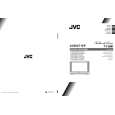
AV28CT1EKS / AV28CT1EKB AV28CT1EPS / AV28CT1EPB AV28CT1EIS
REMOVING THE CRT
� Replacement of the CRT should be performed by 2 or more pers ons. � After removing the c over, chassis etc., 1. Putting the CRT c hange table on soft cloth, the CRT change table should also be c overed with s uch soft cloth (shown in Fig.5). 2. While keeping the s urfac e of CRT down, mount the TV s et on the CRT change table balanced will as shown in Fig.6. 3. Remove 4 sc rews marked by arrows with a box type screw driver as s hown in Fig.6. � Sinc e the cabinet will drop when screws have been removed, be sure to support the cabinet with hands. 4. After 4 screws have been removed, put the cabinet slowly on cloth (At this time, be carefully so as not to damage the front surfac e of the c abinet) shown in Fig.7. � The CRT should be ass embled according to the opposite sequence of its dismounting steps. � The CRT change table should preferably be smaller that the CRT surfac e, and its height be about 35c m. CRT CHANGE TABLE BOX TYPE SCREW DRIVER CRT CHANGE TABLE
APPROX. 35cm
CLOTH
Fig. 5
CRT
COATING OF SILICON GREASE FOR ELECTRICAL INSULATION ON THE CRT ANODE CAP SECTION.
� Subsequent to replac ement of the CRT and HV transformer or repair of the anode cap, etc. by dis mounting them, be sure to coat silicon grease for electrical insulation as shown in Fig.8. Wipe around the anode button with clean and dry cloth. (Fig.8) Coat silic on greas e on the section around the anode button. At this time, take c are so that any silicon greas es dose not stic k to the anode button. (Fig.9) � Silicon grease product No. KS - 650N
Fig. 6
CRT
CABINET
CRT CHANGE TABLE
Fig. 7
CRT
Anode button
Approx. 20mm (Do not coat grease on this s ection
Silic on greas e should be coated by 5mm or more from the outs ide diameter of anode c ap.
Silic on greas e coating
Anode button (No sticking of silicon grease)
Coating position of silicon grease
Anode cap
Fig. 8
Fig. 9
10
No. 51952
|
|
|
> |
|