|
|
|
Categories
|
|
Information
|
|
Featured Product
|
|
|
 |
|
|
There are currently no product reviews.
 ;
Fully functional usable service manual. Considering the age of the manual and device quality was better than expected
 ;
Thank you very much, I've been very happy to find this manual on "Owner Manual". It's a perfect copy and it has been really useful for my work!
;
It took about 24-hours after my payment before I was able to get to the download. Apparently, payment processing is not 100% automated. That is no big deal, just be aware of that going in.
After I got to it, it was in good shape, easy to read, etc. Not some cheap FAX copy looking thing.
Also, this site was the cheapest I found. Another Plus!
;
Good price, very legible manual, exactly what I needed -- but had to wait a day to actually get the download of the manual. Would have preferred to download it immediately after payment rather than waiting for someone to "process" my order. I was surprised that I had to wait that long.
;
As the only source for this manual it rather rank quite high since it is well scanned and perfectly readable.
AV28L2EUGR AV28L2EUBL AV28L2EUGY
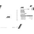
REMOVING THE CRT
$ Replacement of the CRT should be performed by 2 or more persons. ! 1. 2. 3. After removing the cover, chassis etc., Putting the CRT change table on soft cloth, the CRT change table should also be covered with such soft cloth (shown in Fig.4). While keeping the surface of CRT down, mount the TV set on the CRT change table balanced will as shown in Fig.5. Remove 4 screws marked by arrows with a box type screw driver as shown in Fig.5. CRT CHANGE TABLE
APPROX. 35cm
CLOTH
! Since the cabinet will drop when screws have been removed, be sure to support the cabinet with hands. 4. After 4 screws have been removed, put the cabinet slowly on cloth (At this time, be carefully so as not to damage the front surface of the cabinet) shown in Fig.6. ! The CRT should be assembled according to the opposite sequence of its dismounting steps. $ The CRT change table should preferably be smaller that the CRT surface, and its height be about 35cm. $ About CRT Spacer An appropriate CRT spacer should be used in the corresponding CRT in accordance with the type of the CRT. When a CRT is replaced, special attention should be paid to this matter.
Fig. 4
Fig. 5
CRT
COATING OF SILICON GREASE FOR ELECTRICAL INSULATION ON THE CRT ANODE CAP SECTION.
! Subsequent to replacement of the CRT and HV transformer or repair of the anode cap, etc. by dismounting them, be sure to coat silicon grease for electrical insulation as shown in Fig.7. Wipe around the anode button with clean and dry cloth. (Fig.7) Coat silicon grease on the section around the anode button. At this time, take care so that any silicon greases dose not stick to the anode button. (Fig.8)
CABINET
CRT CHANGE TABLE
Fig. 6
� Silicon grease product No. KS - 650N CRT Anode button Approx. 20mm (Do not coat grease on this section Silicon grease should be coated by 5mm or more from the outside diameter of anode cap.
Silicon grease coating
Anode button (No sticking of silicon grease)
Coating position of silicon grease Anode cap
Fig. 7
Fig. 8
8
No. 51778
|
|
|
> |
|