|
|
|
Categories
|
|
Information
|
|
Featured Product
|
|
|
 |
|
|
There are currently no product reviews.
 ;
Very usefully, I could find the trouble clearly with that manual.
;
Bon produit. Permet de corriger les couleurs et de redonnez un petit coup de jeune à vos vieilles vidéos. On regrettera juste le manque d'une prise s-vidéo.
 ;
Quality scan of the actual service manual, just what I was looking for.
;
Straightforward ordering process. Service manual scan was clear & easy to read. Very comprehensive instructions for alignment. Excellent, thank you.
;
Fast, clear and useful. Important for me: the manual is in German.
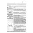
AV-29BF11ENS AV-29BF11EPS AV-29BF11EES
SPECIFIC SERVICE INSTRUCTIONS
DISASSEMBLY PROCEDURE
REMOVING THE REAR COVER
1. Remove the 8 screws marked A. 2. Remove the 4 screws marked B. 3. Withdraw the rear cover toward you.
CHECKING THE PW BOARD
To check the back side of the PW Board. 1) Pull out the PW Board. (Refer to REMOVING THE MAIN PWB). 2) Erect the PW Board vertically so that you can easily check the back side of the PW Board. [CAUTION] " When erecting the PW Board, be careful so that there will be no contacting with other PW Board. " Before turning on power, make sure that the wire connector is properly connected. " When conducting a check with power supplied, be sure to confirm that the CRT EARTH WIRE (BRAIDED ASS�Y) is connected to the CRT SOCKET PW board.
REMOVING THE MAIN PWB
" Removing the rear cover. 1. Slightly raise the both sides of the chassis by hand and withdraw MAIN PWB back ward. [CAUTIONS] If necessary, take off the wire clamp, connectors etc. Be careful enough when developing a main chassis.
REMOVING THE FRONT AV & HEADPHONE BOARD ASS�Y
" Removing the rear cover. " Removing the MAIN PWB. 1. Remove the 2 screws marked C, and remove the FRONT AV & HEADPHONE BOARD ASS�Y.
WIRE CLAMPING AND CABLE TYING
1. Be sure to clamp the wire. 2. Never remove the cable tie used for tying the wires together. Should it be inadvertently removed, be sure to tie the wires with a new cable tie.
REMOVING THE FRONT CONTROL PWB
" Removing the rear cover. " Removing the MAIN PWB. 1. Remove the 3 screws marked D, and remove the FRONT CONTROL PWB.
REMOVING THE WOOFER and TWEETER
" 1. 2. 3. Removing the rear cover. Remove the 4 screws marked E, and remove the WOOFER. Remove the 2 screws marked F, and remove the TWEETER. Remove an opposite side similarly.
REMOVING THE MAIN SWITCH
" Removing the rear cover. " Removeing MAIN PWB. 1. Remove the 2 screws marked G, and remove the MAIN SWITCH.
6
No.52084
|
|
|
> |
|