|
|
|
Categories
|
|
Information
|
|
Featured Product
|
|
|
 |
|
|
There are currently no product reviews.
 ;
Veramente completo, dettagliato e perfetto nella visione. Perfect, thanks!
 ;
Fully functional usable service manual. Considering the age of the manual and device quality was better than expected
;
Thank you very much, I've been very happy to find this manual on "Owner Manual". It's a perfect copy and it has been really useful for my work!
;
It took about 24-hours after my payment before I was able to get to the download. Apparently, payment processing is not 100% automated. That is no big deal, just be aware of that going in.
After I got to it, it was in good shape, easy to read, etc. Not some cheap FAX copy looking thing.
Also, this site was the cheapest I found. Another Plus!
;
Good price, very legible manual, exactly what I needed -- but had to wait a day to actually get the download of the manual. Would have preferred to download it immediately after payment rather than waiting for someone to "process" my order. I was surprised that I had to wait that long.
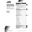
AV-29L31
DISASSEMBLY PROCEDURE [AV-29L31/T]
REMOVING THE REAR COVER
1. Unplug the AC power cord. 2. Remove the 16 screws marked � as shown in Fig.2. 3. Withdraw the Rear cover toward you. [CAUTION] When reinstalling the rear cover, carefully push it inward after inserting the Main PWB into the rear cover groove.
CHECKING THE MAIN PW BOARD
1. To check the back side of the Main PWB. 1) Pull out the chassis. (Refer to REMOVING THE CHASSIS). 2) Erect the chassis vertically so that you can easily check the back side of the Main PWB. [CAUTION] When erecting the chassis, be careful so that there will be no contacting with other PW Board. Before turning on power, make sure that the CRT earth wire and other connectors are properly connected. When repairing, connect the Deg. coil to the DEG. connector on the Main PWB.
�
REMOVING THE CHASSIS (CHASSIS BASE AND CONTROL BASE)
� � �
� After removing the rear cover.
1. Slightly raise the both sides of the chassis by hand and remove the 2 claws marked ı under the chassis from the front cabinet as shown in Fig.2. 2. Withdraw the chassis backward. (If necessary, take off the wire clamp, connector�s etc.)
WIRE CLAMPING AND CABLE TYING
1. Be sure to clamp the wire. 2. Never remove the cable tie used for tying the wires together. Should it be inadvertently removed, be sure to tie the wires with a new cable tie.
* When conducting a check with power supplied, be sure to confirm
that the CRT earth wire is connected to the CRT SOCKET PWB and the Main PWB.
REMOVING THE AV TERMINAL BOARD
� After removing the rear cover.
1. Remove the 4 screws marked � as shown in Fig.2. 2. When you pull out the AV Terminal board in the direction of arrow marked � as shown in Fig.2, it can be removed.
REMOVING THE CONTROL BASE
� After removing the rear cover and the chassis.
1. While pushing down the 2 claws maked ´ as shown in Fig. 3 and pull out the Control base in the direction of arrow maked � as shown in Fig. 3, the control base can be removed. (If necessary, take off the wire, connector�s etc.)
REMOVING THE SPEAKER
� After removing the rear cover.
1. Remove the 4 screws marked � and 2 screws maked � as shown in Fig.2. 2. Withdraw the speaker backward. 3. Follow the same steps when removing the other hand speaker.
8
No. 51926
|
|
|
> |
|