|
|
|
Categories
|
|
Information
|
|
Featured Product
|
|
|
 |
|
|
There are currently no product reviews.
 ;
This Service manual is very well scanned and its clean to read, no any anti-theft words that un-english could understand. I got my CCD600 working with this manual and it´s clear shematics :)
;
I was very pleased with the service provided and was surprised at how good the quality was of the manual. I thought it may be a third generation copy or so, but it is as good as the websites that charge 3 times this much. I repair some electronics for family and friends without charge, so this is perfect for me. Thank you very much.
;
The service was great and the document was also great. Highly recommend!!!!
If anyone has a users manual... Please email me. need one. $ [email protected]
;
I needed a service manual as the display on my oscilloscope was very dim. I thought I'd give owner-manuals.com a try, as they advertised a huge number of manuals. Sure enough they had one listed. I bought it hoping it would be useful... actually, I bought it hoping it would be readable! I've had manuals from online sources in the past, and been very disappointed. Not this time! An excellent manual, complete, and very readable. Using it I fixed my 'scope, and as such the manual was an investment that paid off manyfold. Do I have any complaints? One very minor one - The circuit diagrams could have been scanned at a higher resolution, as some of the details were a little difficult to make out - not impossible, just not as easy as my old eyes would like! Overall, I'm very satisfied with my manual, and I will certainly be using this company again. Well done.
 ;
I Have looked for this manual for quiet a while now, I have finally found it here. I believe this is the only place they have them in a very nice scan, pages are very clear to read, some of the pages are a bit tilted but overall it is great to have this manual available for purchase. Thanks
AV-29L31
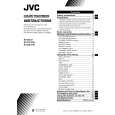
DISASSEMBLY PROCEDURE [AV-29L31/T]
REMOVING THE REAR COVER
1. Unplug the AC power cord. 2. Remove the 16 screws marked � as shown in Fig.2. 3. Withdraw the Rear cover toward you. [CAUTION] When reinstalling the rear cover, carefully push it inward after inserting the Main PWB into the rear cover groove.
CHECKING THE MAIN PW BOARD
1. To check the back side of the Main PWB. 1) Pull out the chassis. (Refer to REMOVING THE CHASSIS). 2) Erect the chassis vertically so that you can easily check the back side of the Main PWB. [CAUTION] When erecting the chassis, be careful so that there will be no contacting with other PW Board. Before turning on power, make sure that the CRT earth wire and other connectors are properly connected. When repairing, connect the Deg. coil to the DEG. connector on the Main PWB.
�
REMOVING THE CHASSIS (CHASSIS BASE AND CONTROL BASE)
� � �
� After removing the rear cover.
1. Slightly raise the both sides of the chassis by hand and remove the 2 claws marked ı under the chassis from the front cabinet as shown in Fig.2. 2. Withdraw the chassis backward. (If necessary, take off the wire clamp, connector�s etc.)
WIRE CLAMPING AND CABLE TYING
1. Be sure to clamp the wire. 2. Never remove the cable tie used for tying the wires together. Should it be inadvertently removed, be sure to tie the wires with a new cable tie.
* When conducting a check with power supplied, be sure to confirm
that the CRT earth wire is connected to the CRT SOCKET PWB and the Main PWB.
REMOVING THE AV TERMINAL BOARD
� After removing the rear cover.
1. Remove the 4 screws marked � as shown in Fig.2. 2. When you pull out the AV Terminal board in the direction of arrow marked � as shown in Fig.2, it can be removed.
REMOVING THE CONTROL BASE
� After removing the rear cover and the chassis.
1. While pushing down the 2 claws maked ´ as shown in Fig. 3 and pull out the Control base in the direction of arrow maked � as shown in Fig. 3, the control base can be removed. (If necessary, take off the wire, connector�s etc.)
REMOVING THE SPEAKER
� After removing the rear cover.
1. Remove the 4 screws marked � and 2 screws maked � as shown in Fig.2. 2. Withdraw the speaker backward. 3. Follow the same steps when removing the other hand speaker.
8
No. 51926
|
|
|
> |
|