|
|
|
Categories
|
|
Information
|
|
Featured Product
|
|
|
 |
|
|
There are currently no product reviews.
 ;
hat alles sehr gut geklappt. Das Servicemaual ist gut zu verwenden. Die Pläne und Schrift
ist klar und leserlich. Außerdem preiswert. Grüße an alle Hifi-Bastler
;
I got the manual quickly after the payment was transfered (1 day). The manual was exactly what i needed and the updates via e-mail were great. Thanx!
;
I've looked for this manual all over that internet, you guys had it and to a good price. A++++
;
I've looked some time for this manual, you guys had it and to a good price. A++++
 ;
factory technician level - complete with board views :
( removing chassis from cabinet , only thing missing ) ;
on weekends , staff is not available so - be patient .
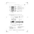
AV-25L91
STATIC CONVERGENCE ADJUSTMENT [AV-25L91-BK]
1. Input a crosshatch signal. 2. Using 4-pole convergence magnets, overlap the red and blue lines in the centre of the screen (Fig. 7) and turn them to magenta (red/ blue). 3. Using 6-pole convergence magnets, overlap the magenta(red/blue) and green lines in the centre of the screen and turn them to white.
(FRONT VIEW) (FRONT VIEW)
Fig. 7
4. Repeat 2 and 3 above, and make best convergence.
TOP
DYNAMIC CONVERGENCE ADJUSTMENT [AV-25L91-BK]
BOTTOM
1. Move the deflection yoke up and down to adjust the pin cushion distortion in the screen top and bottom. (Fig. 8)
(FRONT VIEW)
Fig. 8
2. Using the YV VR on the deflection yoke, match the YV. (Fig. 9)
RED
GREEN BLUE YV BLUE
GREEN RED RED GREEN BLUE
3. Using the YH VR on the deflection yoke, match the YH (CROSS). (Fig. 7 and 12) 4. Repeat the steps 1 and 3 and obtain an optimum convergence. 5. Differential coil ADJUSTMENT. In case where the horizontal lines of red and blue around the centre of both sides of the picture as shown in Fig. 11, adjust the XV difference by using the differential coil on the top of the deflection yoke (Fig. 12) so as to minimize the XV difference.
BLUE GREEN RED YV Fig. 9 (FRONT VIEW) RED YH GREEN BLUE
� After adjustment, fix the wedge at the original position.
Fasten the retainer screw of the deflection yoke. Fix the 6 magnets with glue.
RED GREEN
RED GREEN BLUE
YV VR
YH VR
BLUE
BLUE
GREEN YH
RED
FRONT XV coil
(FRONT VIEW) Fig. 10
Fig. 12
Xv
GREEN
Fig. 11
46
No. 51898
|
|
|
> |
|