|
|
|
Categories
|
|
Information
|
|
Featured Product
|
|
|
 |
|
|
There are currently no product reviews.
 ;
This manual is very useful because it presents the technical specifications of the cd player, including the manufacturer of the reader, this helps if you need to replace it. It also displays the settings and layout of the circuit.
;
Manual was a good representation of service infomation for the EWV404. It worked well for my repair.
 ;
Great quality copy, right what I was looking for, all I need to fix my radio.
Thanks
;
I BOUGHT A PAIR OF INFINITY VINTAGE SPEAKERS THAT REQUIRED TO BE REPAIRED AND THE ELECTRONIC TECHNICIAN ASKED ME FOR THE SERVICE MANUAL.
I TRIED TO GET IT AT THE MANUFACTURER'S SITE WITH NO SUCCESS, SO I STARTED TO LOOK FOR IT IN THE WEB FOR A LONG TIME, UNTIL I FOUND THE SERVICE MANUAL IN THIS EXCELLENT SITE "OWNER'S MANUAL.COM".
NOW I HAVE MY SPEAKERS WORKING AND ENJOYING THE MUSIC I LIKE.
THANKS TO "OWNER`S MANUAL.COM" I RECOMMEND THIS SITE TO EVERYONE.
;
Very quick response. Very good and accurate print quality of the scanned document.
AV-29M201
ADJUSTMENT OF MTS CIRCUIT
Item MTS INPUT LEVEL check Measuring instrument Test point Adjustment part No.2 IN LEVEL Description 1. Select the �No.2 IN LEVEL� of the SOUND mode in SERVICE MENU. 2. Verify that the �No.2 IN LEVEL� is set at its initial setting value. MTS STEREO VCO adjustment Signal generator Frequency counter R OUT No.3 FH MON [AUDIO OUT] No.4 ST VCO 1. Receive a NTSC RF signal (non modulated sound signal) from the antenna terminal. 2. Select the �No.3 FH MON� of SOUND mode in SERVICE MENU, change the setting value from 0 to 1. 3. Connect the frequency connector to R OUT RCA pin of the AUDIO OUT. 4. Select the �No.4 ST VCO�. 5. Confirm the initial setting value of the �No.4 ST VCO�. 6. Adjust the �No.4 ST VCO� so that the frequency counter will display 15.73kHz± 0.1kHz. 7. Select the �No.3 FH MON� of the SOUND mode, and reset the setting value from 1 to 0. MTS SAP VCO adjustment Signal generator Frequency counter MPX No.9 5FH MON. 1. Receive a NTSC RF signal (non modulated sound signal) from the antenna terminal. 2. Connect between pin 4 of MPX connector and GND
Connector 4 pin SDA No.10 SAP VCO. 3 pin GND [MAIN PWB] R OUT [AUDIO OUT]
(pin 3 of MPX connector) through 1MΩ resistor. 3. Select the �No.9 5FH MON.� of the SOUND mode in SERVICE 4. 5. 6. 7. MENU, and reset the setting value from 0 to 1. Connect the frequency connector to R OUT RCA pin of the AUDIO OUT. Select the �No.10 SAP VCO�. Confirm the initial setting value of �No.10 SAP VCO�. Adjust the �No.10 SAP VCO� so that the frequency connector will display 78.67kHz±0.5kHz. 8. Select the �No.9 5FH MON.� of the SOUND mode, and reset the setting value from 1 to 0.
MTS FILTER check
No.6 FILTER
1. Select the �No.6 FLTER� of the SOUND mode in SERVICE MENU. 2. Verify that the �No.6 FLTER� is set at its initial setting value.
MTS SEPARATION adjustment
TV audio multiplex signal generator Oscilloscope
L OUT No.7 LOW SEP. R OUT [AUDIO OUT] No.8 HI SEP.
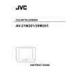
1. Input a stereo L signal (300Hz) from the TV Audio multiplex signal generator to the antenna terminal. (NTSC) 2. Connect an oscilloscope to L OUT RCA pin of the AUDIO OUT, and display one cycle portion of the 300Hz signal. 3. Change the connection of the oscilloscope to R OUT RCA pin of the AUDIO OUT, and enlarge the voltage axis. 4. Select the �No.7 LOW SEP.� of the SOUND mode in SERVICE MENU. 5. Confirm the initial setting value of the �No.7 LOW SEP.�. 6. Adjust the �No.7 LOW SEP.� so that the stroke element of the 300Hz signal will become minimum. 7. Change the signal to 3kHz, and similarly adjust the �No.8 HI SEP.�.
L-Channel signal waveform
R-Channel crosstalk portion Minimum
1 cycle
No. 51731
23
 $4.99 AV29M201 JVC
Owner's Manual Complete owner's manual in digital format. The manual will be available for download as PDF file aft…
|
|
|
> |
|