|
There are currently no product reviews.
 ;
Very complete and well reading drawings. Documentation is essential for successful repairs.Good documentation, with all that is necessary. This manual was what I was waiting with all the information necessary for the repairing I need it for. You must buy it if you want to do repairs or simply understand how it works.
 ;
Excellent service manual includes everything is need to repair this radio-caseete, how to disassemble, wiring diagram, all , waiting time until the download was only a few hours. I'm going to buy service manuals from here, are cheap and very good.Thank you.
;
Good service manual,i saved from scrapping this deck,is now fully functional.Thanks.
;
Found this to be the manual included with the original packinging, was helpfull but did not give any detailed repair instructions.
;
Complete service manual, was very helpful in repairing this tapedeck.Thanks.
AV-32230 AV-32260
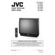
REPLACEMENT OF CHIP COMPONENT
a CAUTIONS
1. 2. 3. 4. Avoid heating for more than 3 seconds. Do not rub the electrodes and the resist parts of the pattern. When removing a chip part, melt the solder adequately. Do not reuse a chip part after removing it.
a SOLDERING IRON
1. Use a high insulation soldering iron with a thin pointed end of it. 2. A 30w soldering iron is recommended for easily removing parts.
a REPLACEMENT STEPS
1. How to remove Chip parts
Resistors, capacitors, etc. (1) As shown in the figure, push the part with tweezers and alternately melt the solder at each end.
2. How to install Chip parts
Resistors, capacitors, etc. (1) Apply solder to the pattern as indicated in the figure.
(2) Grasp the chip part with tweezers and place it on the solder. Then heat and melt the solder at both ends of the chip part. (2) Shift with tweezers and remove the chip part.
Transistors, diodes, variable resistors, etc. (1) Apply extra solder to each lead.
Transistors, diodes, variable resistors, etc. (1) Apply solder to the pattern as indicated in the figure. (2) Grasp the chip part with tweezers and place it on the solder. (3) First solder lead A as indicated in the figure.
SOLDER
SOLDER
A B
(2) As shown in the figure, push the part with tweezers and alternately melt the solder at each lead. Shift and remove the chip part.
C
(4) Then solder leads B and C.
A B C
Note : After removing the part, remove remaining solder from the pattern.
12
No. 51802C
|