|
|
|
Categories
|
|
Information
|
|
Featured Product
|
|
|
 |
|
|
There are currently no product reviews.
 ;
Received a quick response, material was exactly what it was supposed to be. The service did everything I expected it to do. would use service again.
;
Detailed SONY CFD980 Service Manual at an easy to find one stop shopping. Make my radio hobby technically interesting. Thanks.
 ;
Excellent service from Owner-Manuals.com, good prices and quick turn around. The supplied PDF was good enough quality to be enlarged sufficiently to read component values.
;
Very complete shop manual. It contains everything needed to troubleshoot bascially any problem. Instructions, diagrams, schmeatics, illustrations... it's all there. Highly recommended!
;
Great product, very good quality, found all needed information. Thanks
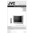
4.7.6 VIDEO CIRCUIT � The adjustment using the remote control unit is made on the basis of the initial setting values. � The setting values which adjust the screen to the optimum condition can be different from the initial setting values. � Do not change the initial setting values of the items not listed in ADJUSTMENT PROCEDURE. Item WHITE BALANCE (Low Light) Measuring instrument Signal generator Remote control unit Test point Adjustment part [7.LOW LIGHT] S01 : BRIGHT S11 : R CUTOFF S12 : G CUTOFF S13 : B CUTOFF SCREEN VR [In HVT] Description (1) Receive a black and white signal (color off). (2) Select the 1.V/C(S). (3) Confirm the initial setting value of <S11>(R CUTOFF), <S12>(G CUTOFF),<S13>(B CUTOFF) and <S01>(BRIGHT) (4) Select the 7.LOW LIGHT. (5) Display a single horizontal line by pressing the [1] key . (6) Turn the SCREEN VR all the way to the left. (7) Turn the SCREEN VR gradually to the right from the left until either one of the red, blue or green colors appears faintly. (8) Use the [4]~[9] keys and adjust the other 2 colors which except the appeared color to where the single horizontal line appears white. (9) Turn the SCREEN VR to where the single horizontal line glows faintly. (10) Press the [2] key to release the single horizontal line. (11) Adjust the bright level to become the black component shines white slightly. (12) Confirm that whether the color ingredient of R, G or B is visible to the black component, which shines white slightly. (13) When the color ingredient can be seen, two colors other than a visible color are adjusted, and it is made to look white. (14) Return the value of bright to initial setting value. (15) Press the [3] key to exit the WHITE BALANCE MODE.
R CUTOFF
B CUTOFF BRIGHT G CUTOFF
BRIGHT
LOW LIGHT ADJUSTMENT MODE
REMOTE CONTROL UNIT SINGLE HORIZONTAL LINE
H.LINE ON H.LINE OFF EXIT
Setting item S11 : R CUT OFF S12 : G CUT OFF S13 : B CUT OFF S01 : BRIGHT
Initial setting value 30 30 30 64
R CUTOFF
G CUTOFF
B CUTOFF
R CUTOFF
G CUTOFF
B CUTOFF
(No.52121)1-27
|
|
|
> |
|