|
|
|
Categories
|
|
Information
|
|
Featured Product
|
|
|
 |
|
|
There are currently no product reviews.
 ;
Very good quality, prompt response. This website has reasonable prices and wide range of manuals that are hard to find.
;
The document was usefull, and it was exactly what I was looking for.
;
OK?..manual is complet and helpfull... for repairing such a old and rare boombox like JVC PCM it is necessary...
;
Super Anleitung. Ordentliche Auflösung. Das ganze noch in Deutsch wäre zu schön. Alle Datenblätter sind sauber Kopiert und alle Leitungswege sind sauber ausgeführt
;
Thanks God for the internet and thanks for the service like this - proffessional solution on time.
AV-32D503 AV-32D303 AV-32D203
SPECIFIC SERVICE INSTRUCTIONS
DISASSEMBLY PROCEDURE
REMOVING THE REAR COVER
" Unplug the power plug. 1. As s hown in Fig.2, remove the
REMOVING THE SPEAKER
" After removing the rear cover and chassis base. 1. As s hown in Fig.2, r emove the
12 screws marked !.
4 screws marked ) .
2. Remove the rear c over toward you. Note : When reinstalling the rear cover, c arefully pus h it inward after inserting the chassis into the rear c over groove.
2. Follow the s ame steps when removing the other hand speaker.
CHECKING THE MAIN PW BOARD
1. To check the backs ide of the MAIN PW Board. (1) Pull out the c hassis base. (Refer to REMOVING THE CHASSIS BASE). (2) Erect the chassis vertic ally so that you can easily chec k from the backside of the MAIN PWB.
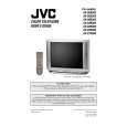
REMOVING THE CHASSIS BASE
" After removing the rear cover. remove the 1. Slightly raise the both s ides of the chassis base by hand, and
2 claws
marked " (Fig.1 and Fig.2) under the both
sides of the chassis from the chassis rail. 2. As shown in Fig.1, draw the chassis base backward along the chassis rail marked # in the arrow direction marked $(Fig.2.). (If necess ary, detac h the wire clamp, connec tor�s etc.) Note : When conducting a c hec k with power supplied, be sure to confirm that the CRT earth wire is c onnected to the CRT SOCKET PWB and the MAIN PWB.
CAUTION
" When erecting the chass is, be c areful so that there will be no contacting with other PWB. " Before turning on power, make sure that the CRT earth wire and other connectors are properly connected.
WIRE CLAMPING AND CABLE TYING
1. Be sure to clamp the wire. 2. Never remove the c able tie used for tying the wires together. Should it be inadvertently removed, be sure to tie the wires with a new c able tie.
REMOVING THE TERMINAL BOARD
" After removing the rear cover. 1. As s hown in Fig.2, remove the
4 screws marked%& . %&
2. When you pull out the TERMINAL BOARD, it can be removed. FRONT CABINET
REMOVING THE FRONT CONTROL PW BOARD
" After removing the rear cover and chassis base . 1. As s hown in Fig.2, remove the
MAIN PWB
2 screws
marked ' attached the
FRONT CONTROL PWB with the front cabinet. 2. Then remove the FRONT CONTROL PWB.
C REMOVING THE FRONT AV IN PW BOARD
" After removing the rear cover and chassis base. 1. As s hown in Fig.2, remove the
2 screws marked ( .
CHASSIS BASE
2. Then remove the FRONT AV IN PW B.
B
Fig. 1
8
No. 51947
|
|
|
> |
|