|
|
|
Categories
|
|
Information
|
|
Featured Product
|
|
|
 |
|
|
There are currently no product reviews.
 ;
Great quality complete service manual! complete parts list and drawings. Thanks!
;
Very good quality, prompt response. This website has reasonable prices and wide range of manuals that are hard to find.
;
The document was usefull, and it was exactly what I was looking for.
;
OK?..manual is complet and helpfull... for repairing such a old and rare boombox like JVC PCM it is necessary...
;
Super Anleitung. Ordentliche Auflösung. Das ganze noch in Deutsch wäre zu schön. Alle Datenblätter sind sauber Kopiert und alle Leitungswege sind sauber ausgeführt
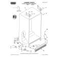
AV32S2EKGR AV32S2EKBL AV32S2EIGR
SPECIFIC SERVICE INSTRUCTIONS
DISASSEMBLY PROCEDURE
REMOVING THE REAR COVER
1. 2. 3. 4. Unplug the power cord. Remove the 4 screw caps from rear cover as shown in Fig.1. Then remove 11 screws marked �A� as shown in the Fig. 1. Withdraw the rear cover toward you.
CHECKING THE PW BOARD
To check the back side of the PW Board. 1) Pull out the chassis. (Refer to REMOVING THE CHASSIS). 2) Erect the chassis vertically so that you can easily check the back side of the PW Board. [CAUTION] " When erecting the chassis, be careful so that there will be no contacting with other PW Board. " Before turning on power, make sure that the wire connector is properly connected. " When conducting a check with power supplied, be sure to confirm that the CRT EARTH WIRE (BRAIDED ASS�Y) is connected to the CRT SOCKET PW board.
REMOVING THE SIDE CONTROL JACK ASSEMBLY
" After removing the rear cover. 1. Remove the screw marked B as shown in the Fig.1. 2. While slightly raise the side control jack assembly, remove the 2 claws under the side control jack assembly. 3. Disconnect the connector �SR�, �SL�, �S�, �F� and �K� as shown in Fig 2.
REMOVING THE SIDE CONTROL PWB
" After removing the rear cover and side control jack assembly. 1. Remove the 3 claws �C� from back side of the side control jack assembly as shown in Fig.2. 2. Pull out the SIDE CONTROL PWB.
WIRE CLAMPING AND CABLE TYING
1. Be sure to clamp the wire. 2. Never remove the cable tie used for tying the wires together. Should it be inadvertently removed, be sure to tie the wires with a new cable tie.
REMOVING THE CHASSIS
" After removing the rear cover. 1. Slightly raise the both sides of the chassis by hand and remove the two claws under the both sides of the chassis from the front cabinet. 2. Withdraw the chassis backward. (If necessary, take off the wire clamp, connectors etc.) Connector SR
C
SL S F SIDE CONTROL PWB
REMOVING THE SPEAKER BOX
" After removing the rear cover. 1. Remove the 2 screws marked �D� as shown in Fig. 1. NOTE : When removing the screws marked D of the speaker box assembly, remove the lower side screw first, and then remove the upper one. 2. Remove the 2 screws �E� attaching the speaker box. 3. Remove the 2 screws �F� attaching the speaker. 4. Follow the same steps when removing the other hand speaker. K
C Fig. 2
J
AV TERMINAL BOARD
I
REMOVING THE AV TERMINAL BOARD
" After removing the rear cover. 1. Remove the 3 screws marked �G� as shown in the Fig. 1. 2. Remove the claws marked �H� under the CHASSIS as shown in Fig. 3. 3. While raising the claw marked �I�, remove the top of the AV TERMINAL BOARD slightly in the direction of arrow �J� as shown in Fig. 3.
H
H Fig. 3
AV SEL. PWB
6
No.51804
|
|
|
> |
|