|
|
|
Categories
|
|
Information
|
|
Featured Product
|
|
|
 |
|
|
There are currently no product reviews.
 ;
- Very good scan quality, PERFECT!
- Sehr gute scan Qualitaet, empfehlenswert!
Wolfgang Sundhaus
 ;
Good site, works ok and you get what you order, no problems experienced, got my manual within a day. A++++
;
Original well scanned manual. Got the job done. Microwave problem found & corrected. For $5 and a new magnitron from ebay, it was a cheap and good the first shot fix. Electrical schematics allowed me to mage sure every thing else was ok before cutting and order for parts. Hard to live without.
;
I was very skeptical of this website, I have never downloaded manuals before. I put it on the AMEX and payed through Paypal to ensure protection. I got the manual exactly as described and now I can replace the filter capacitor for this amp. Great Price, others selling for 12.99 or more and this is the same manual. I will search out this website for other manuals. Thank you
;
Manual was reasonably easy to follow. I am not an engineer or know much about electronics but with the manuals help I was able to figure out the problem, identify the part required for the repair. Replacement part cost around $30. Whilst replacing the part I was telling myself, "this aint gonna work cos it seems far too easy". Took about 15 minutes to do and my plasma TV works a treat. Would never have been able to do this without the service manual.
3.2
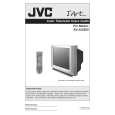
DISASSEMBLY PROCEDURE [AV-32S575 / AV-32S585] 3.2.6 REMOVING THE DIGITAL INPUT MODULE PWB � Remove the REAR COVER � Remove the AV TERMINAL BOARD. (1) Remove the 1 screw [F] and 1 screw [G] as shown in Fig.4. (2) Remove the DIGITAL INPUT MODULE PWB. NOTE: If necessary, take off the wire clamps, connectors etc. CAUTION AT DISASSEMBLY
3.2.1 REMOVING THE REAR COVER � Unplug the power plug. (1) Remove the 13 screws [A] as shown in Fig.4. (2) Remove the REAR COVER toward you. NOTE: When reinstalling the REAR COVER, carefully push it inward after inserting the chassis into the REAR COVER groove.
3.2.2 REMOVING THE SPEAKER � Remove the REAR COVER. (1) Remove the 2 screws [D] as shown in Fig.4, then remove the SPEAKER toward you. (2) Follow the same steps when removing the other hand SPEAKER. 3.2.3 REMOVING THE AV TERMINAL BOARD � Remove the REAR COVER. (1) Remove the 4 screws [B] and 1 screw [C] as shown in Fig.4. (2) Withdraw the AV TERMINAL BOARD toward you.
AV TERMINAL BOARD DIGITAL INPUT MODULE PWB
1 3 5
2 4 6
SB connector
3.2.4 REMOVING THE CHASSIS � Remove the REAR COVER. (1) Slightly raise the both sides of the CHASSIS by hand and remove the 2 claws under the both sides of the CHASSIS from the front cabinet. (2) Withdraw the CHASSIS backward. (If necessary, remove the wire clamps, connectors etc.)
� Prior to disassembly, unplug the power plug from the AC outlet without fail. (Turn the power "off".) � Short the SB connector [1] pin and [2] pin of the DIGITAL INPUT MODULE PWB. (At the time of assembling) � Before the rear cover is inserted into the cabinet, release the short-circuit between the SB connector [1] pin and [2] pin of the DIGITAL INPUT MODULE PWB. � After releasing the short-circuit between the SB connectors, do not turn the power on until the rear cover is inserted into the cabinet. � Negligence in carrying out the above steps may cause the inactivation of the TV.
3.2.5 REMOVING THE CONTROL BASE � Remove the REAR COVER. Remove the CHASSIS. (1) While pushing down the claws [b] as shown in Fig.3. (2) Remove the CONTROL BASE in the arrow direction marked [c]. ( If necessary, remove the wire clamps, connectors etc. )
c b CLAW CONTROL BASE
3.2.7 CHECKING THE PW BOARD � To check the PW Board from backsid. (1) Pull out the CHASSIS. (Refer to REMOVING THE CHASSIS). (2) Erect the CHASSIS vertically with the HVT side facing up so that you can easily check the back side of the PW Board. CAUTION: � When erecting the CHASSIS, be careful so that there will be no contact with other PWB. � Before turning the power on, make sure that the CRT earth wire and other connectors are properly connected.
CHASSIS BASE
Fig.3
3.2.8 WIRE CLAMPING AND CABLE TYING (1) Be sure to clamp the wire. (2) Never remove the cable tie used for tying the wires together. Should it be inadvertently removed, be sure to tie the wires with a new cable tie.
1-8 (No.YA093)
|
|
|
> |
|