|
|
|
Categories
|
|
Information
|
|
Featured Product
|
|
|
 |
|
|
There are currently no product reviews.
 ;
Found the quality of the copy excellent and a very quick service. I would certainly recommend the service.
;
Good quality, clear diagrams. Exactly what I needed.
 ;
Good product. All the information is invcluded, but due to the complexity of the amplifier, it still is difficult to get it to operation again.
;
Very professional seller; very fast, accurate and rielable service.
;
great works fine, got the manual on mail within a day
3.2
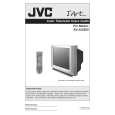
DISASSEMBLY PROCEDURE [AV-32S575 / AV-32S585] 3.2.6 REMOVING THE DIGITAL INPUT MODULE PWB � Remove the REAR COVER � Remove the AV TERMINAL BOARD. (1) Remove the 1 screw [F] and 1 screw [G] as shown in Fig.4. (2) Remove the DIGITAL INPUT MODULE PWB. NOTE: If necessary, take off the wire clamps, connectors etc. CAUTION AT DISASSEMBLY
3.2.1 REMOVING THE REAR COVER � Unplug the power plug. (1) Remove the 13 screws [A] as shown in Fig.4. (2) Remove the REAR COVER toward you. NOTE: When reinstalling the REAR COVER, carefully push it inward after inserting the chassis into the REAR COVER groove.
3.2.2 REMOVING THE SPEAKER � Remove the REAR COVER. (1) Remove the 2 screws [D] as shown in Fig.4, then remove the SPEAKER toward you. (2) Follow the same steps when removing the other hand SPEAKER. 3.2.3 REMOVING THE AV TERMINAL BOARD � Remove the REAR COVER. (1) Remove the 4 screws [B] and 1 screw [C] as shown in Fig.4. (2) Withdraw the AV TERMINAL BOARD toward you.
AV TERMINAL BOARD DIGITAL INPUT MODULE PWB
1 3 5
2 4 6
SB connector
3.2.4 REMOVING THE CHASSIS � Remove the REAR COVER. (1) Slightly raise the both sides of the CHASSIS by hand and remove the 2 claws under the both sides of the CHASSIS from the front cabinet. (2) Withdraw the CHASSIS backward. (If necessary, remove the wire clamps, connectors etc.)
� Prior to disassembly, unplug the power plug from the AC outlet without fail. (Turn the power "off".) � Short the SB connector [1] pin and [2] pin of the DIGITAL INPUT MODULE PWB. (At the time of assembling) � Before the rear cover is inserted into the cabinet, release the short-circuit between the SB connector [1] pin and [2] pin of the DIGITAL INPUT MODULE PWB. � After releasing the short-circuit between the SB connectors, do not turn the power on until the rear cover is inserted into the cabinet. � Negligence in carrying out the above steps may cause the inactivation of the TV.
3.2.5 REMOVING THE CONTROL BASE � Remove the REAR COVER. Remove the CHASSIS. (1) While pushing down the claws [b] as shown in Fig.3. (2) Remove the CONTROL BASE in the arrow direction marked [c]. ( If necessary, remove the wire clamps, connectors etc. )
c b CLAW CONTROL BASE
3.2.7 CHECKING THE PW BOARD � To check the PW Board from backsid. (1) Pull out the CHASSIS. (Refer to REMOVING THE CHASSIS). (2) Erect the CHASSIS vertically with the HVT side facing up so that you can easily check the back side of the PW Board. CAUTION: � When erecting the CHASSIS, be careful so that there will be no contact with other PWB. � Before turning the power on, make sure that the CRT earth wire and other connectors are properly connected.
CHASSIS BASE
Fig.3
3.2.8 WIRE CLAMPING AND CABLE TYING (1) Be sure to clamp the wire. (2) Never remove the cable tie used for tying the wires together. Should it be inadvertently removed, be sure to tie the wires with a new cable tie.
1-8 (No.YA093)
|
|
|
> |
|