|
|
|
Categories
|
|
Information
|
|
Featured Product
|
|
|
 |
|
|
There are currently no product reviews.
 ;
Excellent transaction - clean document received - Thanks a lot
;
Manual is in German but complete. I needed this one to fix a long lasting problem with the internal PSU of the camera. Most of the capacitors begin to leak after a few years wich results in the inability to power on the camera. When you try to turn it on the power led flickers and the unit directly turns off. Thanks to this manual I was able to locate all bad cap's and to dis- and reassemble the camera without any problems.
 ;
We received the manual in a timely manner and it was exactly what we were expecting.
;
Excellant, finally this is want I need and searching for The service manual is fantastic and thank you to owner-manuals.com and its service. Price is reasonable. It's a bit slow on my end in downloading but manage to receive the whole manual without a break. once again, thanks.
;
Very good scanning quality. All schematics are very legible. Worth every cent !
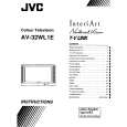
AV-32WL1EU AV-32WL1EI AV-32WL1EK
REMOVING THE CRT
Replacement of the CRT should be performed by 2 or more persons. After removing the cover, chassis etc.. 1. Putting the CRT change table on soft cloth, the CRT change table should also be covered with such soft cloth (shown in Fig.5). 2. While keeping the surface of CRT down, mount the TV set on the CRT change table balanced will as shown in Fig.5. 3. Remove 4 screws marked by arrows with a box type screw driver as shown in Fig.6. Since the cabinet will drop when screws have been removed, be sure to support the cabinet with hands. 4. After 4 screws have been removed, put the cabinet slowly on cloth (At this time, be carefully so as not to damage the front surface of the cabinet) shown in Fig.7. The CRT should be assembled according to the opposite sequence of its dismounting steps. The CRT change table should preferably be smaller that the CRT surface, and its height be about 35cm. CLOTH CRT CHANGE TABLE
APPROX. 35cm
Fig. 5 CRT
CRT CHANGE TABLE BOX TYPE SCREW DRIVER
Fig. 6
CRT
COATING OF SILICON GREASE FOR ELECTRICAL INSULATION ON THE CRT ANODE CAP SECTION.
Subsequent to replacement of the CRT and HV transformer or repair of the anode cap, etc. by dismounting them, be sure to coat silicon grease for electrical insulation as shown in Fig.8. Wipe around the anode button with clean and dry cloth. (Fig.8) Coat silicon grease on the section around the anode button. At this time, take care so that any silicon greases dose not stick to the anode button. (Fig.9) � Silicon grease product No. KS - 650N CRT Anode button Approx. 20mm (Do not coat grease on this section Silicon grease should be coated by 5mm or more from the outside diameter of anode cap. Fig. 7 CABINET CRT CHANGE TABLE
Silicon grease coating
Anode button (No sticking of silicon grease)
Coating position of silicon grease
Anode cap
Fig. 8
Fig. 9
12
No. 51733
|
|
|
> |
|