|
|
|
Categories
|
|
Information
|
|
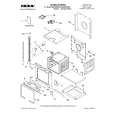
Featured Product
|
|
|
 |
|
|
There are currently no product reviews.
 ;
the manual is in quite good quality and it's in pdf. manual was send in less then 6h.
 ;
Absolutely top, I've got now all Service-Manuals I'll need to repair my Mackie-Mixer!
;
The service manuel is very helpful, we where able to restore the device to its working operation again.
;
Great quality complete service manual!!! complete parts list and drawings
;
Again a great job. I never been disilluted from them! Clear scheme, complete and very good for repairing!
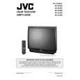
AV-36230 AV-36260
REMOVING THE CRT
* Replacement of the CRT should be performed by 2 or more persons.
CRT CHANGE TABLE
� After removing the rear cover, chassis etc.,
1. Putting the CRT change table on soft cloth, the CRT change table should also be covered with such soft cloth (shown in Fig. 2). 2. While keeping the surface of CRT down, mount the TV set on the CRT change table balanced will as shown in Fig. 3. 3. Remove 4 screws marked by arrows with a box type screwdriver as shown in Fig. 3. Since the cabinet will drop when screws have been removed, be sure to support the cabinet with hands. 4. After 4 screws have been removed, put the cabinet slowly on cloth (At this time, be carefully so as not to damage the front surface of the cabinet) shown in Fig. 4. The CRT should be assembled according to the opposite sequence of its dismounting steps.
APPROX. 35cm CLOTH
�
Fig. 2
�
CRT
* The CRT change table should preferably be smaller that the CRT surface, and its height be about 35cm.
CRT CHANGE TABLE BOX TYPE SCREW DRIVER
Fig. 3
CRT
COATING OF SILICON GREASE FOR ELECTRICAL INSULATION ON THE CRT ANODE CAP SECTION
� Subsequent to replacement of the CRT and HV transformer or repair
of the anode cap, etc. by dismounting them, be sure to coat silicon grease for electrical insulation as shown in Fig. 5. Wipe around the anode button with clean and dry cloth. (Fig. 5) Coat silicon grease on the section around the anode button. At this time, take care so that any silicon greases does not sticks to the anode button. (Fig. 6) Silicon grease product No. KS - 650N
Approx. 20mm (Do not coat grease on this section Silicon grease should be coated by 5mm or more from the outside diameter of anode cap.
CABINET
CRT CHANGE TABLE
Fig. 4
CRT
Anode button
Silicon grease coating
Anode button (No sticking of silicon grease)
Coating position of silicon grease Anode cap
Fig. 5
Fig. 6
No. 51801C
9
|
|
|
> |
|