|
|
|
Categories
|
|
Information
|
|
Featured Product
|
|
|
 |
|
|
There are currently no product reviews.
 ;
It's a good manual, this one it's a scan from the original factory service manual, great quality 100% readeable. definetely it worths what I paid for.
 ;
A good manual! fast service and good qualityi for pdf document.
thanks!
;
Very helpful and complete manual. Maybe only one negative is schematics have sometimes unreadable name of the parts. But it's not a big problem.
;
Excellent high quality schematics brought my old Heidelberg back to life. Fast download at a reasonable price. Thanks.
;
This document is just what I was looking for, it´s very useful, it contains adjustment procedures for the final stage of the power amp and also
has a complete wiring diagram and description of the main semiconductors used in the design.
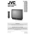
AV-36360 AV-36S36 AV-36330 AV-36S33 AV-36320
REPLACEMENT OF CHIP COMPONENT
! CAUTIONS
1. 2. 3. 4. Avoid heating for more than 3 seconds. Do not rub the electrodes and the resist parts of the pattern. When removing a c hip part, melt the s older adequately. Do not reuse a chip part after removing it.
! SOLDERING IRON
1. Use a high ins ulation s oldering iron with a thin pointed end of it. 2. A 30w s oldering iron is rec ommended for easily removing parts.
! REPLACEMENT STEPS
1. How to remove Chip parts # Resistors, capacitors, etc (1) As shown in the figure, push the part with tweezers and alternately melt the solder at each end.
2. How to install Chip parts
# Resistors, capacitors, etc (1) Apply solder to the pattern as indic ated in the figure.
(2) Shift with tweezers and remove the chip part.
(2) Grasp the chip part with tweezers and plac e it on the s older. Then heat and melt the solder at both ends of the chip part.
# Transistors, diodes, variable r esistor s, etc (1) Apply extra solder to each lead.
# Transistors, diodes, variable r esistor s, etc (1) Apply solder to the pattern as indic ated in the figure. (2) Grasp the chip part with tweezers and place it on the solder. (3) First s older lead A as indicated in the figure.
SOLD E R
SOLD E R
A (2) As shown in the figure, push the part with tweezers and alternately melt the solder at each lead. Shift and remove the chip part. B C (4) Then solder leads B and C.
A B Note : After removing the part, remove remaining solder from the pattern. C
No.51950
13
|
|
|
> |
|