|
There are currently no product reviews.
 ;
So far I´m a satisfied customer. I have only downloaded "TECHNICS SX-KN470 Service Manual" maybe I will use it later.
Best regards
Peter
;
Good manual. It is complete and of high quality, both text and graphics. The schematics are with the original big size, so it can be viewed or printed without any loss of resulution and sharpness.
;
We needed a manual quickly...online it was available immediately, at a very low price. We loved the convenience!
;
Excellent!!
Got what I need and very fast!!
Thank You
;
One address for rare manuals.Very good copy. Thank you.
Your
Klaus Husse
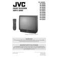
AV-36360 AV-36S36 AV-36330 AV-36S33 AV-36320
REPLACEMENT OF CHIP COMPONENT
! CAUTIONS
1. 2. 3. 4. Avoid heating for more than 3 seconds. Do not rub the electrodes and the resist parts of the pattern. When removing a c hip part, melt the s older adequately. Do not reuse a chip part after removing it.
! SOLDERING IRON
1. Use a high ins ulation s oldering iron with a thin pointed end of it. 2. A 30w s oldering iron is rec ommended for easily removing parts.
! REPLACEMENT STEPS
1. How to remove Chip parts # Resistors, capacitors, etc (1) As shown in the figure, push the part with tweezers and alternately melt the solder at each end.
2. How to install Chip parts
# Resistors, capacitors, etc (1) Apply solder to the pattern as indic ated in the figure.
(2) Shift with tweezers and remove the chip part.
(2) Grasp the chip part with tweezers and plac e it on the s older. Then heat and melt the solder at both ends of the chip part.
# Transistors, diodes, variable r esistor s, etc (1) Apply extra solder to each lead.
# Transistors, diodes, variable r esistor s, etc (1) Apply solder to the pattern as indic ated in the figure. (2) Grasp the chip part with tweezers and place it on the solder. (3) First s older lead A as indicated in the figure.
SOLD E R
SOLD E R
A (2) As shown in the figure, push the part with tweezers and alternately melt the solder at each lead. Shift and remove the chip part. B C (4) Then solder leads B and C.
A B Note : After removing the part, remove remaining solder from the pattern. C
No.51950
13
|