|
|
|
Categories
|
|
Information
|
|
Featured Product
|
|
|
 |
|
|
There are currently no product reviews.
 ;
This is a good quality scan of the service manual which includes an assembly diagram, block diagram, schematic, and parts list. Exactly what is needed to repair my KR-V55R receiver.
;
Excellent concise manual. All needed information was included. Typeface and diagrams were clear. Very fair price considering what others are charging. Many thanks
 ;
Response is a little slow- I had to wait 12 hours to receive download link but it says that it may take up to 24hrs.
Manual is old and was not produced in PDF- scanned copy is exellent.
Overall- value for money- I recommend
;
Excellent quality and quickly delivered manuals at a fair price. Great care is taken in the reproduction process. Even photographs and highly detailed drawings are as clear as in the original. That cannot be said for some freelance manual copies I have obtained from the web. If you have exhausted your internet search of technical manuals, try Owner-Manuals.com. If they do not have it, I do not think it exists. Perhaps, if requested, they may be able to find it. Their resources are certainly greater than most. Shopping here certainly beats waiting for months or years for the manual you seek to appear in an internet auction or garage sale.
;
Very detailed product, also it is a scanning from original, very useful if you have to service this type of amplifier ! Very good product, very hard to find!
AV-36D202 AV-36D302 AV-36D502
SPECIFIC SERVICE INSTRUCTIONS
DISASSEMBLY PROCEDURE
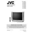
REMOVING THE REAR COVER
1. Unplug the power supply cord. 2. Remove the 12 screws marked A as shown in Fig.1. 3. Withdraw the REAR COVER toward you. [CAUTION] When reinstalling the rear cover, carefully push it inward after inserting the MAIN PWB into the rear cover groove.
REMOVING THE SPEAKER
� After removing the rear cover.
1. Remove the 4 screws marked H as shown in Fig.1. 2. Withdraw the speaker backward. 3. Follow the same steps when removing the other hand speaker.
�
CHECKING THE MAIN PW BOARD REMOVING THE CHASSIS
1. To check the back side of the MAIN PW Board. 1) Pull out the chassis. (Refer to REMOVING THE CHASSIS). 2) Erect the chassis vertically so that you can easily check the back side of the MAIN PW Board. [CAUTION] When erecting the chassis, be careful so that there will be no contacting with other PW Board. Before turning on power, make sure that the CRT earth wire and other connectors are properly connected.
� After removing the rear cover.
1. Slightly raise the both sides of the chassis by hand and remove the 3 claws marked B under the chassis from the front cabinet as shown in Fig.1. 2. Withdraw the chassis backward along the rail in the arrow direction marked C as shown in Fig.1. (If necessary, take off the wire clamp, connector�s etc.)
� �
* When conducting a check with power supplied, be sure to confirm
that the CRT earth wire is connected to the CRT SOCKET PWB and the MAIN PWB.
WIRE CLAMPING AND CABLE TYING
1. Be sure clamp the wire. 2. Never remove the cable tie used for tying the wires together. Should it be inadvertently removed, be sure to tie the wires with a new cable tie.
REMOVING THE TERMINAL BOARD
� After removing the rear cover.
1. Remove the 4 screws marked D as shown in Fig.1. 2. When you pull out the TERMINAL BOARD in the direction of arrow marked E as shown in Fig.1, it can be removed.
REMOVING THE FRONT CONTROL AND FRONT AV INPUT PW BOARDS
� After removing the rear cover and chassis.
1. Remove the 3 screws marked F and the 2 screws marked G as shown in Fig.1. 2. Then remove the FRONT CONTROL PWB and FRONT AV INPUT PWB. (If necessary, take off the wire, connector�s etc.)
8
No. 51798C
|
|
|
> |
|