|
|
|
Categories
|
|
Information
|
|
Featured Product
|
|
|
 |
|
|
There are currently no product reviews.
 ;
The Manual was perfect.
The deliverie was perfect.
Thanks
;
Found website easy to use and manual very clear. First class service
 ;
The quality is quite good and clear. Nothing of the informations inside is lost during the digitalizing process
;
Very good service, fast downloads and good manuals.
;
Good qulity. Even as it is an old manual (from 1991-1992) it has a good scanned quality and is complete, including user's manual, disassembly intructions, diagrams and schematics, ajustments, troubleshooting and parts list, as usual with SONY manuals and Owner-manuals service.
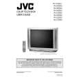
AV-36D202 AV-36D302 AV-36D502
SPECIFIC SERVICE INSTRUCTIONS
DISASSEMBLY PROCEDURE
REMOVING THE REAR COVER
1. Unplug the power supply cord. 2. Remove the 12 screws marked A as shown in Fig.1. 3. Withdraw the REAR COVER toward you. [CAUTION] When reinstalling the rear cover, carefully push it inward after inserting the MAIN PWB into the rear cover groove.
REMOVING THE SPEAKER
� After removing the rear cover.
1. Remove the 4 screws marked H as shown in Fig.1. 2. Withdraw the speaker backward. 3. Follow the same steps when removing the other hand speaker.
�
CHECKING THE MAIN PW BOARD REMOVING THE CHASSIS
1. To check the back side of the MAIN PW Board. 1) Pull out the chassis. (Refer to REMOVING THE CHASSIS). 2) Erect the chassis vertically so that you can easily check the back side of the MAIN PW Board. [CAUTION] When erecting the chassis, be careful so that there will be no contacting with other PW Board. Before turning on power, make sure that the CRT earth wire and other connectors are properly connected.
� After removing the rear cover.
1. Slightly raise the both sides of the chassis by hand and remove the 3 claws marked B under the chassis from the front cabinet as shown in Fig.1. 2. Withdraw the chassis backward along the rail in the arrow direction marked C as shown in Fig.1. (If necessary, take off the wire clamp, connector�s etc.)
� �
* When conducting a check with power supplied, be sure to confirm
that the CRT earth wire is connected to the CRT SOCKET PWB and the MAIN PWB.
WIRE CLAMPING AND CABLE TYING
1. Be sure clamp the wire. 2. Never remove the cable tie used for tying the wires together. Should it be inadvertently removed, be sure to tie the wires with a new cable tie.
REMOVING THE TERMINAL BOARD
� After removing the rear cover.
1. Remove the 4 screws marked D as shown in Fig.1. 2. When you pull out the TERMINAL BOARD in the direction of arrow marked E as shown in Fig.1, it can be removed.
REMOVING THE FRONT CONTROL AND FRONT AV INPUT PW BOARDS
� After removing the rear cover and chassis.
1. Remove the 3 screws marked F and the 2 screws marked G as shown in Fig.1. 2. Then remove the FRONT CONTROL PWB and FRONT AV INPUT PWB. (If necessary, take off the wire, connector�s etc.)
8
No. 51798C
|
|
|
> |
|