|
|
|
Categories
|
|
Information
|
|
Featured Product
|
|
|
 |
|
|
There are currently no product reviews.
 ;
reasonable price for the schematic - the service is perfect, all as expected and pointed by instructions - good scan of the original plans - thank you!
;
Manual was just as described!!! I odered it and in less than a day was able to download it and the text was clear and pages were all complete just as the original manual was. Purcashed this for a friend and they were more than happy. Perfect all around!
 ;
Excellent service and prompt delivery. But it's not a manual - only 4 pages wiring diagrams.
Thanks.
;
The manual I purchased was exactly what I needed to repair my Toshica television. The manual contained schematics and troubleshooting information that was very helpful.
;
Il download del Service Manual JVC HR 4100 non é stato eseguito
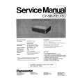
3.1.10 REAR PANEL (1) Loosen 4 screws [ M ]. (2) Remove 4 screws [ N ]. (3) Raise slightly REAR PANEL upward. (4) Take out the REAR PANEL. NOTE : � Before the rear panel is inserted into the cabinet, release the short-circuit between the [SB] connector (1) pin and (2) pin of the DIGITAL INPUT UNIT. (Refer to "CAUTION AT DISASSEMBLY" on Page 14). � After releasing the short-circuit between the [SB] connectors, do not turn the power on until the rear panel is inserted into the cabinet. � Prior to starting the work, be sure to read the following written instructions on the CAUTION LABEL attached to the REAR PANEL. Prior to starting the work, be sure to read the following written instructions on the CAUTION LABEL attached to the REAR PANEL. UNPLUG THE POWER CORD FROM AC OUTLET BEFORE OPEN THE REAR COVER (PANEL). When the rear cover (panel) is removed, follow "CAUTION AT DISASSEMBLY" procedure in the service manual before plugging the TV's power cord into an AC outlet. Failure to follow the procedure will result in PERMANENT damage to some of the television features. 3.1.11 REAR COVER BRACKET (1) Remove 2 screws [ O ]. (2) Take out the REAR COVER BRACKET. 3.1.12 PARTITION � Take out the REAR PANEL. (1) Pull out the PARTITION back ward. 3.1.13 REAR COVER � Take out the SPEAKER GRILLE. � Take out the FRONT CONTROL BOX. � Take out the SCREEN ASS'Y. (1) Remove 2 screws [ P ]. (2) Remove 2 screws [ Q ] from front side. (3) Slightly pull for backside to disengage of the REAR COVER from hooks. (4) Take out the REAR COVER. NOTE : � Because of the large size, at least two persons are recommended for removal and reassemble.
PARTITION
M O N M
REAR PANEL
REAR COVER BRACKET
Fig.6
REAR COVER
Q P
Q
Fig.7
(No.52168)1-15
|
|
|
> |
|